1. Goal
In the first post I set up an LSP between the PEs with OSPF and LDP, in the second I put VPLS on top of it. In this post I set up a VPRN on top of the same core.
The goal: two different customers should use the same IP range (both have 192.168.1.0/24 and 192.168.2.0/24), and still not see each other’s traffic. Same PEs, same core, but the customers completely separate from each other.
2. What is VPRN, how is it different from VPLS?
In VPLS the service provider carries L2 for the customer: the CEs talk as if they were connected to the same switch, and the PE knows nothing about IP. In VPRN the service is L3: the PE speaks routing with the customer’s router and keeps a separate routing table for the customer.
Think of it like an apartment building. The building (the MPLS core) is shared by everyone. But every customer has their own floor (VPRN) and their own floor plan (route table). Both floors can have a “room number 3”, they don’t get mixed up.
The parts:
- VPRN (VRF): The customer-specific routing table on the PE. The customer sees the inside of this table.
- RD (Route Distinguisher): A tag added to the front of the prefix to tell them apart in BGP even if two customers use the same prefix. Instead of
192.168.1.0/24,65200:300:192.168.1.0/24is carried, so it becomes a VPN-IPv4 address. - RT (Route Target): The tag that decides which route goes into which VPRN. The PE takes the route from BGP, looks at its RT and puts it into the matching VPRN.
- MP-BGP (
family vpn-ipv4): The protocol that carries customer routes between PEs. The P router has nothing to do with it.
In the core, a two-layer label comes into play: the outer label is the transport label from LDP (the path to PE2), the inner label is the service label that identifies the customer (which VPRN it will enter). So what we did with the SDP in VPLS, MP-BGP does here.
3. Topology and IP plan
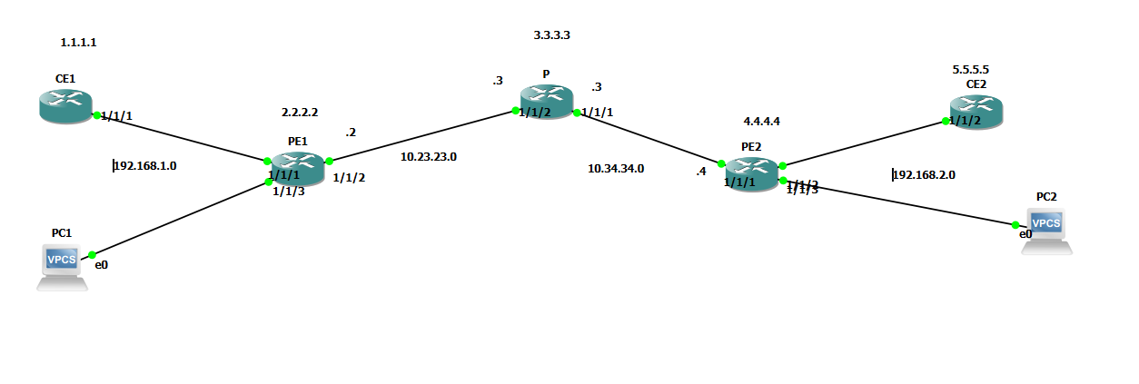
The core is the same as in the previous posts: PE1 2.2.2.2, P 3.3.3.3, PE2 4.4.4.4, 10.23.23.0 between PE1 and P, 10.34.34.0 between P and PE2. OSPF and LDP are already running, I didn’t touch them in this post.
There are two customers and both use the same two subnets:
| Customer A | Customer B | |
|---|---|---|
| VPRN ID | 300 | 400 |
| Customer ID | 10 | 20 |
| RD / RT | 65200:300 | 65200:400 |
| PE1 side | CE1 (1/1/1), 192.168.1.2 | PC1 (1/1/3), 192.168.1.3 |
| PE1 VPRN interface | 192.168.1.1/24 | 192.168.1.1/24 |
| PE2 side | CE2 (1/1/2), 192.168.2.2 | PC2 (1/1/3), 192.168.2.4 |
| PE2 VPRN interface | 192.168.2.1/24 | 192.168.2.1/24 |
I didn’t open separate vSIMs for Customer B, two VPCS were enough. Since VPRN is L3, a host that gives an IP and a gateway does the job, and it doesn’t strain the RAM.
The place to watch: on PE1 I gave 192.168.1.1/24 to two separate interfaces (one in VPRN 300, one in 400). Normally you can’t give the same IP to two interfaces on a router. In VPRN you can, because every VPRN is a separate routing table.
The AS number is 65200, both PEs are in the same AS.
4. Configuration
I went in two stages. First the basic preparation and MP-BGP, then the VPRN service itself.
A1. CEs: IP and default route
The CE is the customer router. Its only job is an interface facing the PE and a default route that says “send everything to the PE”.
CE1:
configure system name "CE1"
configure port 1/1/1 no shutdown
configure router
    interface "toPE1"
        address 192.168.1.2/24
        port 1/1/1
        no shutdown
    exit
    static-route 0.0.0.0/0 next-hop 192.168.1.1
exit
admin save
CE2:
configure system name "CE2"
configure port 1/1/2 no shutdown
configure router
    interface "toPE2"
        address 192.168.2.2/24
        port 1/1/2
        no shutdown
    exit
    static-route 0.0.0.0/0 next-hop 192.168.2.1
exit
admin save
If you gave the CEs another address before (in my case 192.168.10.x), first do no address on that interface, then enter the new address.
A2. Access port and customer on the PEs
On PE1 the port facing the CE is 1/1/1, on PE2 it’s 1/1/2. Before changing the port mode, the port needs to be shut down:
configure port 1/1/1 shutdown
configure port 1/1/1 ethernet mode access
configure port 1/1/1 no shutdown
configure service customer 10 create
    description "MyCustomer"
exit
admin save
The same on PE2, only port 1/1/2.
A3. MP-BGP between the PEs
Since there are two PEs, a single session is enough: PE1 with PE2. We don’t write any BGP on the P router.
PE1:
configure router autonomous-system 65200
configure router bgp
    group "PE"
        family vpn-ipv4
        peer-as 65200
        neighbor 4.4.4.4
            local-address 2.2.2.2
        exit
    exit
    no shutdown
exit
admin save
The same on PE2, neighbor 2.2.2.2, local-address 4.4.4.4.
What the lines mean:
autonomous-system 65200: Both PEs are in the same AS, so the session is iBGP.family vpn-ipv4: Turns on the VPN-IPv4 address family. If you don’t write it, VPRN routes aren’t carried.neighbor 4.4.4.4: The remote PE’s system IP. We skip the P in between and open the session directly.local-address 2.2.2.2: Starts the session from our own system IP. Since the other side expects2.2.2.2as the neighbor, the two must match.
B. VPRN service
VPRN 300 for Customer A on PE1:
configure service vprn 300 customer 10 create
    route-distinguisher 65200:300
    auto-bind-tunnel
        resolution filter
        resolution-filter
            ldp
        exit
    exit
    vrf-target target:65200:300
    interface "toCE1" create
        address 192.168.1.1/24
        sap 1/1/1 create
        exit
    exit
    no shutdown
exit
The info output looks like this (the customer ID isn’t shown in info, it shows up in show service id 300 base):
route-distinguisher 65200:300
auto-bind-tunnel
    resolution-filter
        ldp
    exit
    resolution filter
exit
vrf-target target:65200:300
interface "toCE1" create
    address 192.168.1.1/24
    sap 1/1/1 create
    exit
exit
no shutdown
VPRN 400 on PE1 for Customer B, the same structure, a different RD/RT and interface:
configure service vprn 400 customer 20 create
    route-distinguisher 65200:400
    auto-bind-tunnel
        resolution filter
        resolution-filter
            ldp
        exit
    exit
    vrf-target target:65200:400
    interface "toCE3" create
        address 192.168.1.1/24
        sap 1/1/3 create
        exit
    exit
    no shutdown
exit
PE2 has the same two services. For VPRN 400 the interface is toCE3, the address 192.168.2.1/24, the SAP 1/1/3. For VPRN 300 the interface is toCE2, the address 192.168.2.1/24, the SAP 1/1/2.
What the lines mean:
route-distinguisher 65200:300: The tag added to this VPRN’s routes. 300 for Customer A, 400 for Customer B.vrf-target target:65200:300: Something separate from the RD. A single line used both for export (add this RT when giving the route to BGP) and import (take the routes carrying this RT into this VPRN). It must be the same value on both PEs, otherwise the routes don’t go into the other side’s VPRN.resolution filterandldpunderauto-bind-tunnel: Says which tunnel will carry the VPRN route’s next hop (4.4.4.4). Here I’m saying “use the LSP built with LDP”. Without this the route doesn’t resolve to a tunnel, and the traffic doesn’t go.interface ... sap 1/1/1: The L3 interface facing the customer. The SAP ties the physical port and the service together.
5. Verification
BGP session
show router bgp summary
At the end of stage A the session is up, the VPN-IPv4 family is on, but since there’s no VPRN yet there are no routes, and 0/0/0 (VpnIPv4) shows at the end of the line. Once the two customers were set up, it looked like this on PE1:
Neighbor
Description
                   AS PktRcvd InQ  Up/Down   State|Rcv/Act/Sent (Addr Family)
                      PktSent OutQ
-------------------------------------------------------------------------------
4.4.4.4
                65200      46    0 00h20m55s 2/2/2 (VpnIPv4)
                           48    0
-------------------------------------------------------------------------------
2/2/2: 2 routes received from PE2 (Received), 2 of them active (Active), 2 routes sent to PE2 (Sent). And the routes belong to the two customers: one VPRN 300, one VPRN 400.
VPN routes
show router bgp routes vpn-ipv4
Flag  Network                                            LocalPref   MED
      Nexthop (Router)                                   Path-Id     Label
      As-Path
-------------------------------------------------------------------------------
u*>i  65200:300:192.168.2.0/24                           100         None
      4.4.4.4                                            None        131070
      No As-Path
u*>i  65200:400:192.168.2.0/24                           100         None
      4.4.4.4                                            None        131066
      No As-Path
The flags at the start of the line: u means the route is in use (used), * valid, > the best path was chosen (best), i learned from iBGP.
What stands out in both routes: the same prefix (192.168.2.0/24) appears twice, but the RD in front of them is different (65200:300 and 65200:400). That’s exactly the RD’s job: BGP sees the same prefix as two separate routes. The Label column on the right is the service label PE2 gives separately for each VPRN (131070 and 131066). When the packet passes through the core, this label becomes the inner label, and PE2 looks at it to understand which VPRN to enter. So PE1 received the route PE2 sent, it’s valid and in use.
The same addresses, two separate worlds
show router 300 route-table
show router 400 route-table
Dest Prefix[Flags]                            Type    Proto     Age        Pref
      Next Hop[Interface Name]                                    Metric
-------------------------------------------------------------------------------
192.168.1.0/24                                Local   Local     00h26m14s  0
       toCE1                                                        0
192.168.2.0/24                                Remote  BGP VPN   00h21m14s  170
       4.4.4.4 (tunneled)                                           0
Dest Prefix[Flags]                            Type    Proto     Age        Pref
      Next Hop[Interface Name]                                    Metric
-------------------------------------------------------------------------------
192.168.1.0/24                                Local   Local     00h23m18s  0
       toCE3                                                        0
192.168.2.0/24                                Remote  BGP VPN   00h15m36s  170
       4.4.4.4 (tunneled)                                           0
In both, 192.168.1.0/24 is Local and 192.168.2.0/24 is Remote. The same prefix sits in two separate tables, with one difference: the Local one points to the toCE1 interface in VPRN 300 and to the toCE3 interface in VPRN 400. 4.4.4.4 (tunneled) on the remote route shows that the route goes to PE2 through the LDP tunnel, so auto-bind-tunnel did its job. Proto is BGP VPN, preference 170.
Connectivity test
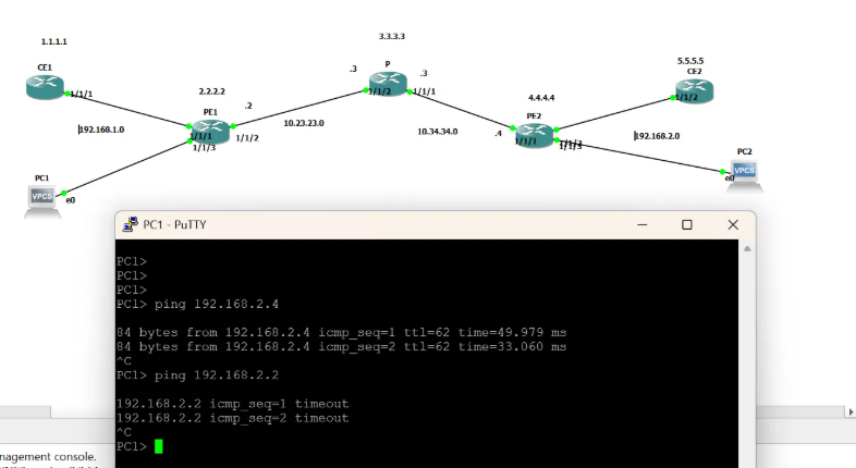
A ping from PC1 between Customer B’s two offices:
ping 192.168.2.4
PC1> ping 192.168.2.4

84 bytes from 192.168.2.4 icmp_seq=1 ttl=62 time=49.979 ms
84 bytes from 192.168.2.4 icmp_seq=2 ttl=62 time=33.060 ms
The ping went through. The TTL came back as 62. Along the way only PE1 and PE2 do work at the IP layer, the P router doesn’t show up because P forwards the packet by looking only at the label.
Isolation test
This is the most important test in the post. A ping from PC1 to the address of Customer A’s CE2:
ping 192.168.2.2
PC1> ping 192.168.2.2

192.168.2.2 icmp_seq=1 timeout
192.168.2.2 icmp_seq=2 timeout
It didn’t go through. 192.168.2.2 is Customer A’s address. There’s no such host in Customer B’s VPRN (400), so the packet doesn’t get anywhere. Same core, same address plan, but the two customers don’t even know the other exists.
6. Where I got stuck
The port mode change gave an error
I got an error while putting the port on the PE into access mode. The mode doesn’t change while the port is up: first shutdown, then ethernet mode access, then no shutdown. If you set up a VPWS or VPLS service on that port before, you also need to remove that service.
The old address was still on the CE
I got an error while entering a new IP on the CE because the old address was still on the interface. First no address, then the new address.
The BGP session stayed in Idle
When I looked at show router bgp summary on PE2, the neighbor 2.2.2.2 was in this state:
Neighbor
                   AS PktRcvd InQ  Up/Down   State|Rcv/Act/Sent (Addr Family)
                      PktSent OutQ
-------------------------------------------------------------------------------
2.2.2.2
                0           0    0 00h00m34s Idle
                            0    0
Two things stand out: State Idle (the router isn’t even trying to connect to the other side, if I saw Connect or Active I would blame the other side) and AS 0 (the neighbor’s AS should have shown as 65200).
The commands that helped with diagnosis:
configure router bgp info
show router bgp neighbor 2.2.2.2
The second one writes the reason it can’t connect in a line like Last Error.
Traffic stayed one-way on PE2
After the service is set up, you need to check whether PE2 also has the auto-bind-tunnel setting like PE1, because otherwise the traffic stays one-way. For this:
show service id 400 base
The output should have these lines:
Auto Bind Tunnel
Resolution        : filter
Filter Protocol   : ldp
7. Summary
- VPRN carries L3 for the customer. The PE keeps a separate routing table for the customer.
- The RD separates the same prefix in BGP even if two customers use it, the RT says which VPRN the route goes into.
- Between the PEs, MP-BGP (
family vpn-ipv4) carries the routes, the P router doesn’t know BGP. - There are two labels in the core: the outer label is the transport from LDP, the inner label is the service (VPRN) label.
- Two customers can use the same IP range; even if
192.168.2.2and192.168.2.4are in the same subnet, different VPRNs don’t see each other. - For diagnosis:
show router bgp summary(the State and AS columns),show router bgp neighbor,show router <vprn-id> route-table.
It was a fun topic and lab :)