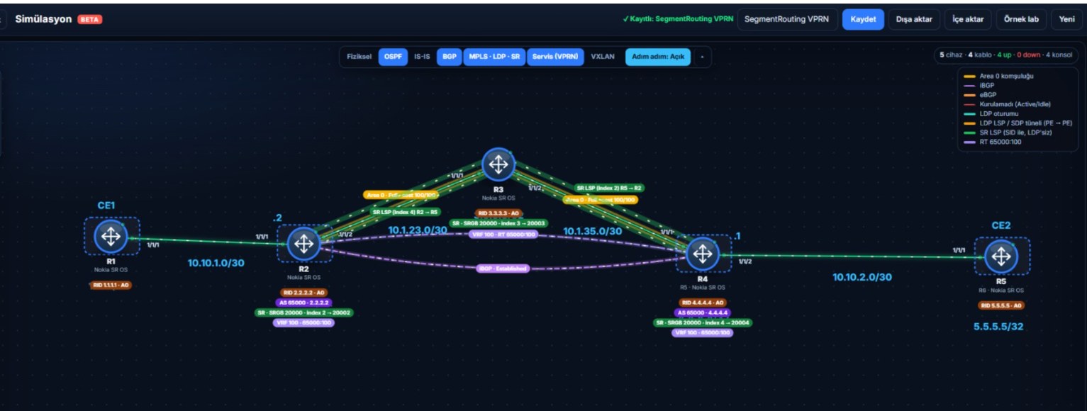
The topology I built in the simulator: R1 = CE1, R2 = PE1, R3 = P, R5 = PE2, R6 = CE2. Details in 6.1.
Version note: The commands in this post use the classic CLI structure
configure service vprn <id> auto-bind-tunnel, and the simulator uses that structure. In newer Nokia releases the same setting also exists underbgp-ipvpn mpls:configure service vprn 100 bgp-ipvpn mpls auto-bind-tunnel resolution filterand... resolution-filter sr-ospf(the 25.7 VPRN documentation contains thebgp-ipvpn mpls auto-bind-tunnelpath). I couldn’t verify in which release the old path was removed, or which one is required in which release. On your own device, look forauto-bind-tunnelwith?first, and try it underbgp-ipvpn mplsif needed.
1. Goal
If you read the concept post first, this post is its command version. If you didn’t, here it is in one sentence: in an L3VPN, the VPN label (MP-BGP) does the “which customer” job and the transport tunnel does the “how do I reach the far PE” job. With SR only the second one changes.
In the VPRN post the core ran LDP. In the SR post we removed LDP and had OSPF distribute the labels. In this post I put the two together: a VPRN running in a core with no LDP.
Goal: ping from CE1’s LAN (192.168.1.1) to CE2’s LAN (192.168.2.1). There’s a trap on the way, and we’ll walk into it on purpose.
2. Topology, IP plan and SID plan
CE1 --- PE1 --- P --- PE2 --- CE2
| Router | Loopback | SID index | SR label (SRGB 20000) | Links |
|---|---|---|---|---|
| CE1 | LAN 192.168.1.1/24 | - | - | 10.10.1.2/30 (to PE1) |
| PE1 | 1.1.1.1/32 | 1 | 20001 | 1/1/1 CE1 (10.10.1.1/30), 1/1/2 P (10.1.12.1/30) |
| P | 2.2.2.2/32 | 2 | 20002 | 1/1/1 PE1 (10.1.12.2/30), 1/1/2 PE2 (10.1.24.1/30) |
| PE2 | 4.4.4.4/32 | 4 | 20004 | 1/1/1 P (10.1.24.2/30), 1/1/2 CE2 (10.10.2.1/30) |
| CE2 | LAN 192.168.2.1/24 | - | - | 10.10.2.2/30 (to PE2) |
AS 65000 (iBGP between the PEs), customer VRF is VPRN 100, RD and RT are 65000:100. I made the loopback number and the SID index the same so it’s easy to remember: 4.4.4.4 → index 4 → label 20004.
3. Configuration: three layers
We build in order: the underlay (IP, OSPF, SR), the service (MP-BGP, VPRN), then the tunnel selection. I’m leaving the third one for last on purpose.
3.1 Underlay: IP, OSPF and SR (PE1)
configure router interface "system" address 1.1.1.1/32
configure port 1/1/2 no shutdown
configure router interface "toP" address 10.1.12.1/30
configure router interface "toP" port 1/1/2

configure router ospf no shutdown
configure router ospf area 0 interface "system" no shutdown
configure router ospf area 0 interface "toP" interface-type point-to-point
configure router ospf area 0 interface "toP" no shutdown

configure router mpls-labels sr-labels start 20000 end 27999
configure router ospf advertise-router-capability area
configure router ospf segment-routing prefix-sid-range global
configure router ospf segment-routing no shutdown
configure router ospf area 0 interface "system" node-sid index 1
The last five lines are SR itself. I explained each one in the SR post: reserve the SRGB, advertise the router capability, turn SR on, give the loopback its index. There is no LDP line. On P and PE2 repeat the same with their own addresses and indexes (P: 2, PE2: 4).
3.2 Service: MP-BGP and VPRN (PE1)
configure router autonomous-system 65000
configure router bgp router-id 1.1.1.1
configure router bgp group "iBGP" peer-as 65000
configure router bgp group "iBGP" local-address 1.1.1.1
configure router bgp group "iBGP" family vpn-ipv4
configure router bgp group "iBGP" neighbor 4.4.4.4
configure router bgp no shutdown

configure port 1/1/1 ethernet mode access
configure port 1/1/1 no shutdown
configure service customer 10 create
configure service vprn 100 customer 10 create
    route-distinguisher 65000:100
    vrf-target target:65000:100
    interface "toCE" create
        address 10.10.1.1/30
        sap 1/1/1 create
        exit
    exit
    static-route-entry 192.168.1.0/24 next-hop 10.10.1.2
    no shutdown
exit all
Every line in this block is in the VPRN post: BGP carries VPN routes with family vpn-ipv4, route-distinguisher and vrf-target separate the customer, sap binds the PE-CE port to the service, static-route-entry teaches the VPRN the CE’s LAN. On PE2 it’s the same: neighbor 1.1.1.1, port 1/1/2, CE address 10.10.2.1, LAN route 192.168.2.0/24 next-hop 10.10.2.2.
On the CEs there’s the address, a LAN interface and a static route to the other LAN:
# CE1
configure port 1/1/1 no shutdown
configure router interface "toPE" address 10.10.1.2/30
configure router interface "toPE" port 1/1/1
configure router interface "LAN" address 192.168.1.1/24
configure router interface "LAN" loopback
configure router static-route-entry 192.168.2.0/24 next-hop 10.10.1.1
Three things to watch:
- The LAN interface must be
loopback. What makes an interface a loopback is theloopbackcommand, not its name. If you name itLoopback1but skip the command, Nokia treats it as a normal interface, expects it to be bound to a port and shows itDown.no shutdowndoesn’t fix that, because the problem isn’t the admin state. - The same address can’t sit on two interfaces. Give the same /24 to a second interface and you get
overlaps with interface. Delete the one opened by mistake and keep the right one. - The PE-CE link lives only in the VPRN. On the PE, don’t bind the customer-facing port to the global router. If you open
toCEin the global router with an IP and later give the same port and address to the VPRN, you get an error: a port can’t be bothnetworkandaccess. If you opened it by mistake, remove it withconfigure router interface "toCE" shutdownandconfigure router no interface "toCE". To set the port toaccessmode the port must beshutdownfirst (must be shutdown before changing the mode).
3.3 Watch out: there is no auto-bind-tunnel
In the VPRN in 3.2 I didn’t say anywhere “which tunnel to use”. That’s deliberate. Let’s see what happens.
4. Verification: find the trap
4.1 Is the underlay healthy?
The tunnel table on PE1:
A:PE1# show router tunnel-table
===============================================================================
IPv4 Tunnel Table (Router: Base)
===============================================================================
Destination       Owner     Encap TunnelId  Pref     Nexthop        Metric
-------------------------------------------------------------------------------
2.2.2.2/32        ospf (0)  MPLS  524289    10       10.1.12.2      100
4.4.4.4/32        ospf (0)  MPLS  524290    10       10.1.12.2      200
-------------------------------------------------------------------------------
Only ospf (0) owners: the SR tunnels. There is no LDP row because we didn’t set up LDP. The SR tunnel to PE2 (4.4.4.4) is ready.
Simulator note: Here the
Ownercolumn saysospf (0). On a real SR OS I know SR tunnels show up assr-ospfin this column, but I couldn’t find a sample output in Nokia’s documentation to confirm it. Check what yours says.
4.2 Is MP-BGP up?
A:PE1# show router bgp summary
...
Neighbor
Description
                   AS PktRcvd InQ  Up/Down   State|Rcv/Act/Sent (Addr Family)
                      PktSent OutQ
-------------------------------------------------------------------------------
4.4.4.4
                65000       4    0 00h00m00s 0/0/2 (VPN-IPv4)
                            3    0
The word Established never appears in the State column. If the session isn’t up, the column shows the state name (Idle, Active, Connect); once it is up, it shows the received/active/sent route counts instead. Here there are numbers: the session is up (the Up/Down timer is running too). 0/0/2 means received/active/sent: PE1 sent 2 VPN routes to PE2. The routes coming from the other side don’t show in the count; I explain why in the simulator note in 4.4.
4.3 Ping fails
A:CE1# ping 192.168.2.1 source 192.168.1.1
PING 192.168.2.1 56 data bytes
Request Timeout. icmp_seq=1.
Request Timeout. icmp_seq=2.
...
5 packets transmitted, 0 packets received, 100% packet loss
4.4 PE1’s VRF table has no remote LAN
A:PE1# show router 100 route-table
===============================================================================
Route Table (Router: 100)
===============================================================================
Dest Prefix[Flags]                            Type    Proto     Age        Pref
      Next Hop[Interface Name]                                    Metric
-------------------------------------------------------------------------------
10.10.1.0/30                                  Local   Local     00h00m00s  0
       toCE                                                         0
192.168.1.0/24                                Remote  Static    00h00m00s  5
       10.10.1.2                                                    0
-------------------------------------------------------------------------------
No. of Routes: 2
Only the two local rows. The 192.168.2.0/24 advertised by PE2 did not enter the table. The service summary gives the clue away:
A:PE1# show service id 100 base
...
Route Dist.       : 65000:100
Vrf Target        : target:65000:100
Auto Bind Tunnel  : none
Auto Bind Tunnel : none. The VPRN hasn’t been told which tunnel to use.
Simulator note: At this stage the simulator doesn’t show the VPN routes coming from PE2 in the BGP table at all (
show router bgp routes vpn-ipv4is empty, it says0/0/2). On a real SR OS the route shows up but is unusable (because the next-hop isn’t resolved). In both cases the common symptom is that the VRF table has no remote route. I’ll add the exact output of a real device when I try it.
4.5 Why is that?
The route PE1 learned from BGP is “192.168.2.0/24, next-hop 4.4.4.4, VPN label X”. To use it, it must be able to reach 4.4.4.4 through a tunnel. On Nokia a VPRN has no default tunnel resolution (Auto Bind Tunnel : none). In the LDP core we also had to write auto-bind-tunnel; we wrote it for LDP in the VPRN post. Here there is an SR tunnel, but the VPRN isn’t allowed to use any tunnel type. The result: the next-hop doesn’t resolve and the route can’t be used.
5. The fix: bind the tunnel to the VPRN
On both PEs:
configure service vprn 100 auto-bind-tunnel resolution filter
configure service vprn 100 auto-bind-tunnel resolution-filter sr-ospf
What the two lines mean:
resolution filter: “Use a filter when selecting a tunnel.” Only the type I tick is valid.resolution-filter sr-ospf: “The allowed type: an SR tunnel programmed by OSPF.”
I wrote these two lines as full paths on purpose. If you enter auto-bind-tunnel and resolution-filter step by step, the contexts get mixed up easily: inside resolution-filter (the res-filter# prompt), typing resolution filter gives Bad command, because that command belongs one level up (auto-bind#). When the command is rejected the setting isn’t applied and there is still no tunnel resolution. If in doubt, type exit all and use the full path. Do it on both PEs: if you do it on only one, that PE sees the remote routes but the return path doesn’t resolve, so the ping still fails.
The alternative is the single line resolution any. It accepts every type (LDP, SR) and looks at the preference value in the tunnel table (Pref). If LDP is also on, LDP is selected (Pref 9 < 10). When LDP goes away, the service moves to a suitable SR tunnel by itself. filter is the sure way of saying “SR only”. During the migration from LDP to SR we use it so it’s clear which tunnel the service is on. The reverse holds too: if before the migration filter allowed only ldp, the service goes down the moment you turn LDP off.
Look at the service summary again:
A:PE1# show service id 100 base
...
Auto Bind Tunnel  : sr-ospf
6. Prove it works
A:CE1# ping 192.168.2.1 source 192.168.1.1
PING 192.168.2.1 56 data bytes
64 bytes from 192.168.2.1: icmp_seq=1 ttl=64 time=25.1ms.
...
5 packets transmitted, 5 packets received, 0.00% packet loss
PE1’s VRF table:
A:PE1# show router 100 route-table
...
10.10.1.0/30                                  Local   Local     00h00m00s  0
       toCE                                                         0
10.10.2.0/30                                  Remote  BGP VPN   00h00m00s  170
       4.4.4.4 (tunneled)                                           0
192.168.1.0/24                                Remote  Static    00h00m00s  5
       10.10.1.2                                                    0
192.168.2.0/24                                Remote  BGP VPN   00h00m00s  170
       4.4.4.4 (tunneled)                                           0
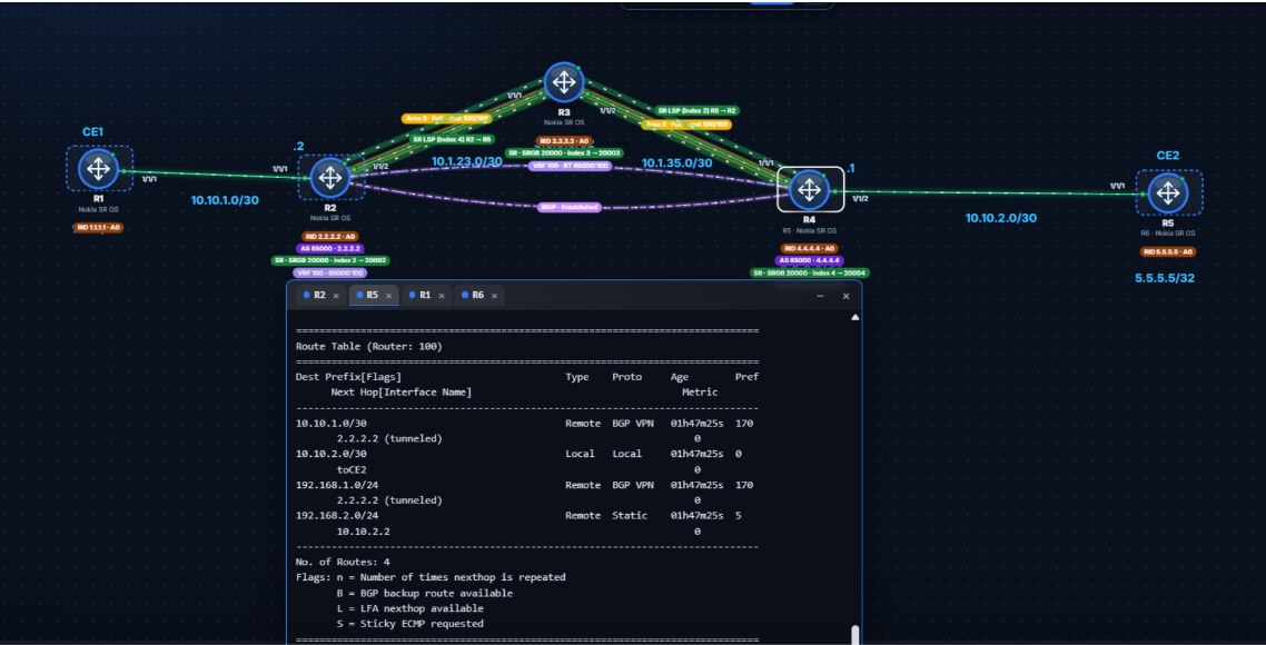
The remote routes arrived as BGP VPN and next to the next-hop it says (tunneled): “this route is reached through a tunnel”. That’s the sign the tunnel resolution works.
6.1 The finished setup in the simulation
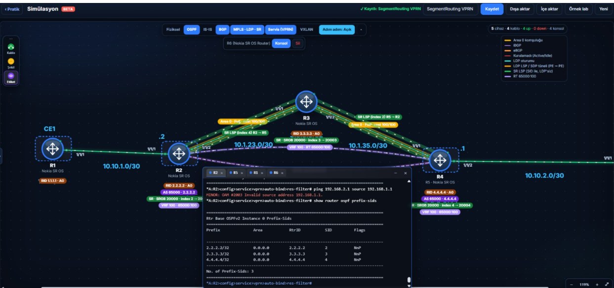
I built the same scenario from scratch on the Simulation page (Turkish UI), screenshots below (the topology map is at the top of the post). In this build the router names are R1–R6: R1 = CE1, R2 = PE1, R3 = P, R5 = PE2, R6 = CE2 (on the map the PE2 box is labelled R4 and the CE2 box R5; that’s the box number, the router’s real name is on the second line and in the CLI prompt: R5, R6). Here the SID indexes are 2, 3 and 4 (same as the last octet of the loopback), so the labels are 20002, 20003 and 20004. The label towards PE2 is still 20004.
The prefix-SIDs SR distributes with OSPF. The NnP flags show Nokia advertises its SIDs as no-PHP:
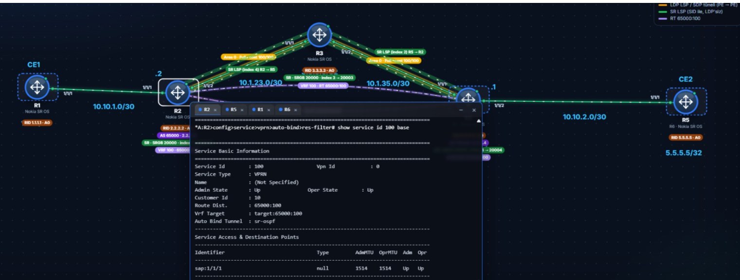
The service summary after the fix. Auto Bind Tunnel is now sr-ospf (the res-filter# in the prompt shows I made the setting inside the resolution-filter context):
PE2’s VRF table. The remote routes are BGP VPN and (tunneled), its own CE’s LAN is Static:
7. Find the two labels
Where are the two labels from the concept post in the tables?
The VPN label: the value PE2 advertised through BGP:
A:PE1# show router bgp routes vpn-ipv4
...
Flag  Network                                            LocalPref   MED
      Nexthop (Router)                                   Path-Id     Label
      As-Path
-------------------------------------------------------------------------------
u*>i  65000:100:10.10.2.0/30                             100         None
      4.4.4.4                                            None        100007
      No As-Path
u*>i  65000:100:192.168.2.0/24                           100         None
      4.4.4.4                                            None        100007
      No As-Path
100007 in the Label column. That’s PE2’s “this packet belongs to VRF 100” label (Nokia’s default label mode is one label per VRF). Note: the 65000:100 at the start of the address is the RD, the label is in a separate column.
The transport label: the SR label, SRGB base + index. For 4.4.4.4 PE1 uses the SR tunnel in show router tunnel-table. The label is 20000 + 4 = 20004 (P’s SRGB base is 20000, PE2’s index is 4).
When the packet leaves PE1 it has 20004 on top and 100007 underneath. P recognises 20004 as PE2’s SID. PE2 is right next to it, but P does not pop the label: Nokia SR OS always advertises its own Prefix-SIDs with the NP-flag (no-PHP) set. P swaps the label to 20004 again for PE2’s SRGB. 20004 + 100007 reach PE2. PE2 first terminates its own SID label 20004, then looks at 100007 and hands the packet to VRF 100.
If PE2 were a Cisco or Huawei, the default would usually be PHP: P would pop the transport label and only the VPN label would go to PE2. That’s why the label stack you capture on the last link can differ by vendor. Note: Nokia’s LDP didn’t do PHP by default either (LDP post).
To follow it hop by hop, run the ping in step-by-step mode on the Simulation page (Turkish UI). For the conceptual animation see the packet path section of the concept post.
8. Break it: turn SR off on P
The data plane depends on the transport tunnel, but the BGP control plane doesn’t. To see this, turn SR off on P:
configure router ospf segment-routing shutdown
On PE1:
A:PE1# show router tunnel-table
...
No Matching Entries.

A:PE1# show router 100 route-table
10.10.1.0/30       Local  Local
192.168.1.0/24     Remote Static
No. of Routes: 2

A:CE1# ping 192.168.2.1 source 192.168.1.1
...
5 packets transmitted, 0 packets received, 100% packet loss
The tunnel table is empty (PE1’s neighbor P no longer speaks SR), the remote routes are gone from the VRF, the ping is down. Meanwhile the PE1-PE2 BGP session is still up: BGP runs over TCP between the loopbacks and the IP route to the loopbacks is still there. So “BGP up” doesn’t mean the VPN works; the transport tunnel is needed too.
Turn it back on:
configure router ospf segment-routing no shutdown
The tunnel returns, the routes come back to the VRF, the ping works.
9. Common mistakes
1. Missing auto-bind-tunnel. The main lesson of this post. Symptom: BGP up, tunnel exists, no remote route in the VRF. In the service summary Auto Bind Tunnel : none.
2. Writing resolution filter but putting nothing inside resolution-filter. In the simulator, with an empty filter no type is allowed and again there is no resolution.
3. Skipping SR on the P router. If SR is on in the PEs and off on P, the tunnel breaks between PE1 and P and there is no tunnel to PE2. Every router must speak SR.
4. Thinking you’re on SR because of resolution any. If LDP is also on, the service picks LDP (Pref 9). Check which tunnel you are on from the Auto Bind Tunnel line and the tunnel table, and make it definite with filter + sr-ospf.
5. Index collision between loopbacks. If two loopbacks get the same index, one is left without a SID (SR post). There is no tunnel to the PE without a SID and the VPN goes down.
6. Blaming the export when the route is missing from BGP. In this simulator, with no tunnel, the VPN route doesn’t even show in the BGP table. I first assumed the static route wasn’t leaving PE2 into BGP and went looking for an export policy, the wrong direction. Once I added auto-bind-tunnel, the route came without any policy. First check whether it says Auto Bind Tunnel : none, then look at the export. I haven’t tried the export behavior on a real device.
7. Typing resolution filter in the wrong context. Inside res-filter# you get Bad command and the setting isn’t applied. Write the full path as in section 5, or exit all first.
8. Opening the PE-CE link in the global router. Opening toCE in the global router and moving it to the VPRN later causes overlap and port mode errors. See the notes in section 3.2.
10. Try it yourself
The same scenario is ready in two versions (both in Turkish):
- The short version: the core and the VPRN come ready,
auto-bind-tunnelis missing. 7 tasks: inspect the underlay, verify BGP, see the trap, fix it, ping, follow the tunnel, turn SR off and on on P. - The from-scratch version: the routers start empty. You build IP, OSPF, SR, MP-BGP and the VPRN yourself, skip the tunnel setting on purpose and fall into the trap on your own. 11 tasks.
The hints don’t name commands, you have to look them up.
The Huawei counterpart: Running L3VPN over SR-MPLS BE (Huawei).
Honest note: These outputs are from the simulator. The commands and columns follow Nokia’s classic CLI, but on a real SR OS some columns may look different (especially the
Ownercolumn in the tunnel table (ospf (0)orsr-ospf), whether BGP VPN routes show up in the table when there is no tunnel, and the label numbers). I’ll add the differences here when I try it on a real device.
11. Summary
- A VPRN works in a core with no LDP, but you have to tell the VPRN which tunnel to use:
auto-bind-tunnel. resolution filter+resolution-filter sr-ospfuses only the SR tunnels programmed by OSPF.resolution anyaccepts LDP and SR together and looks at the preference value.- Symptom: BGP up + SR tunnel present + no remote route in the VRF. In the service summary
Auto Bind Tunnel : none. - When it works the VRF table shows the remote routes as
BGP VPNand(tunneled). - Two labels on the packet: SR on top (20000 + 4 = 20004), the VPN label underneath (the BGP
Labelcolumn, 100007). P only looks at the top one. Because Nokia advertises its SIDs without PHP, P doesn’t pop the label and both labels reach PE2. - When SR is turned off on P the tunnel table empties and the VPN goes down, but BGP stays up.
For the whole series, see MPLS from Scratch (Turkish).