1. Goal
In the previous post I set up an LSP between PE1 and PE2 with OSPF and LDP. Nobody is carrying anything over this path yet. In this post I put a service on that path: VPLS. In the end, CE1 and CE2 will talk as if they were connected to the same switch, without ever knowing there’s an MPLS core between them.
I’m using the same topology, nothing changed.
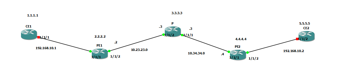
CE1 and CE2 are in the same subnet: 192.168.10.1/24 and 192.168.10.2/24. Since VPLS is a single virtual switch, the two CEs need to be in the same subnet. I don’t run OSPF or any other routing protocol between them, they’re in the same L2 network.
2. Why is an SDP needed when there’s an LSP?
This was the first question that came to my mind: the IGP and LDP already set up an LSP, it’s sitting in the tunnel table, so why doesn’t the service just use it directly?
The answer is that SR OS separates the service layer from the transport layer. The LSP is only the path. The service needs to know separately “which tunnel to take to the remote PE” and “which label to use”. The SDP (Service Distribution Point) does this.
- With
far-endI give the remote PE’s loopback. - With
ldpI say “use the LSP built by LDP when going to this end”. - PE1 and PE2 need to talk between themselves about the service label (VC label). The existing LDP session is only between neighbors (PE1-P, P-PE2). So when the SDP comes up, a targeted LDP session is set up between PE1 and PE2, loopback to loopback.
The SDP isn’t a new tunnel. Underneath it there’s still the same LSP. It’s just the door through which the service layer looks at that LSP.
Cargo analogy
Continuing the cargo analogy from the previous post: the LSP is the truck route between two hubs. The SDP is the cargo company’s contract with the remote hub: “parcels going there will take this route.” VPLS is the service you sell the customer with that contract. A customer barcode (service label) is also stuck on the customer’s parcel, and the hub in the middle (P) only looks at the route barcode, not the customer barcode.
3. Configuration
CE ports
The ports on the CE side are shut down by default in SR OS. I forgot this on my first try, so the interface showed as Down on the CE. The port needs to be opened on both CEs.
CE1
configure port 1/1/1 no shutdown
CE2
configure port 1/1/2 no shutdown
The CE interfaces (192.168.10.1/24 and 192.168.10.2/24) are already defined.
PE1
The port facing the CE must switch to access mode, because this is the door that will put the Ethernet frame from the customer into the service. For the mode change, the port must be shutdown.
configure port 1/1/1
    shutdown
    ethernet
        mode access
    exit
    no shutdown
exit all
Then the service side:
configure service
    customer 1 create
        description "Musteri-1"
    exit

    sdp 12 mpls create
        far-end 4.4.4.4
        ldp
        no shutdown
    exit

    vpls 100 customer 1 create
        sap 1/1/1 create
            no shutdown
        exit
        mesh-sdp 12:100 create
            no shutdown
        exit
        no shutdown
    exit
exit all
PE2
The same, only the port, the SDP number and the far-end are different:
configure port 1/1/2
    shutdown
    ethernet
        mode access
    exit
    no shutdown
exit all

configure service
    customer 1 create
        description "Musteri-1"
    exit

    sdp 21 mpls create
        far-end 2.2.2.2
        ldp
        no shutdown
    exit

    vpls 100 customer 1 create
        sap 1/1/2 create
            no shutdown
        exit
        mesh-sdp 21:100 create
            no shutdown
        exit
        no shutdown
    exit
exit all
What do the commands do?
| Command | What it does |
|---|---|
customer 1 | The customer the service belongs to. Just a label, but SR OS wants it for every service. |
sdp 12 mpls | The service tunnel to PE2. The number only has meaning on this router, on PE2 I write 21. |
far-end 4.4.4.4 | The remote PE’s loopback. |
ldp | Use the LDP LSP for transport. |
vpls 100 | The virtual switch. The number is the service ID. |
sap 1/1/1 | The door through which the customer enters the service. Every frame coming from this port enters the VPLS. |
mesh-sdp 12:100 | Binds the service to the SDP. 12 is the SDP number, 100 is the VC-ID. |
The VC-ID topic confused me. The 100 in 21:100 doesn’t mean “VPLS 100”, it’s the number of the virtual cable. It must be the same on both PEs. The reason it’s the same as the service ID is the default behavior: if the VC-ID isn’t written, the service ID is used (Def. Mesh VC Id : 100 in the output).
More than one service can pass over the same SDP. Every service has its own virtual cable (12:100, 12:200, …) and its own service label. The VC-ID isn’t written on the packets, the PEs only tell each other during setup. In the data plane, what separates them is the service label.
4. Verification
SDP state
A:PE1-R2# show service sdp

============================================================================
Services: Service Destination Points
============================================================================
SdpId  AdmMTU  OprMTU  Far End          Adm  Opr         Del     LSP   Sig
----------------------------------------------------------------------------
12     0       0       4.4.4.4          Up   Down        MPLS    L     TLDP
----------------------------------------------------------------------------
Number of SDPs : 1
----------------------------------------------------------------------------
Legend: R = RSVP, L = LDP, B = BGP, M = MPLS-TP, n/a = Not Applicable
        I = SR-ISIS, O = SR-OSPF
============================================================================
*A:PE2-R4>config>service>vpls# show service sdp

============================================================================
Services: Service Destination Points
============================================================================
SdpId  AdmMTU  OprMTU  Far End          Adm  Opr         Del     LSP   Sig
----------------------------------------------------------------------------
21     0       8914    2.2.2.2          Up   Up          MPLS    L     TLDP
----------------------------------------------------------------------------
Number of SDPs : 1
----------------------------------------------------------------------------
Legend: R = RSVP, L = LDP, B = BGP, M = MPLS-TP, n/a = Not Applicable
        I = SR-ISIS, O = SR-OSPF
============================================================================
Both Adm and Opr should be Up. If you see OprMTU: 0, it means the SDP couldn’t find a tunnel, look at the LDP LSP.
Tunnel table
When the SDP comes up, it also writes itself into the tunnel table:
A:PE1-R2# show router tunnel-table

===============================================================================
IPv4 Tunnel Table (Router: Base)
===============================================================================
Destination       Owner     Encap TunnelId  Pref     Nexthop        Metric
-------------------------------------------------------------------------------
3.3.3.3/32        ldp       MPLS  65537     9        10.23.23.3     100
4.4.4.4/32        sdp       MPLS  12        5        4.4.4.4        0
4.4.4.4/32        ldp       MPLS  65538     9        10.23.23.3     200
-------------------------------------------------------------------------------
Flags: B = BGP backup route available
       E = inactive best-external BGP route
===============================================================================
There are two lines for 4.4.4.4/32: ldp and sdp. The SDP isn’t a tunnel, it’s the entry that looks at the LSP from the service. The path underneath is still the same LDP LSP.
Targeted LDP session
A:PE1-R2# show router ldp session

==============================================================================
LDP IPv4 Sessions
==============================================================================
Peer LDP Id         Adj Type  State         Msg Sent  Msg Recv  Up Time
------------------------------------------------------------------------------
3.3.3.3:0           Link      Established   15        16        0d 00:00:24
4.4.4.4:0           Targeted  Established   8         10        0d 00:00:20
------------------------------------------------------------------------------
No. of IPv4 Sessions: 2
==============================================================================
A Link session with 3.3.3.3 and a Targeted session with 4.4.4.4. The second one is the session the SDP brought, the one that carries the service labels.
VPLS service state
A:PE1-R2# show service id 100 base

===============================================================================
Service Basic Information
===============================================================================
Service Id        : 100                 Vpn Id            : 0
Service Type      : VPLS
Customer Id       : 1                   Creation Origin   : manual
Admin State       : Up                  Oper State        : Up
MTU               : 1514                Def. Mesh VC Id   : 100
SAP Count         : 1                   SDP Bind Count    : 1
...
-------------------------------------------------------------------------------
Service Access & Destination Points
-------------------------------------------------------------------------------
Identifier                               Type         AdmMTU  OprMTU  Adm  Opr
-------------------------------------------------------------------------------
sap:1/1/1                                null         1514    1514    Up   Up
sdp:12:100 M(4.4.4.4)                    Mesh         0       8914    Up   Up
===============================================================================
In the table at the bottom, both the SAP and the SDP bind lines are Up/Up. The M in the sdp:12:100 M(4.4.4.4) line says this is a mesh binding and that the far end is 4.4.4.4. Def. Mesh VC Id: 100 shows that since I didn’t write the VC-ID separately, it took the service number.
To see in a single line that the service is up:
A:PE1-R2# show service service-using

===============================================================================
Services
===============================================================================
ServiceId    Type      Adm  Opr  CustomerId Service Name
-------------------------------------------------------------------------------
100          VPLS      Up   Up   1
2147483648   IES       Up   Down 1          _tmnx_InternalIesService
2147483649   intVpls   Up   Down 1          _tmnx_InternalVplsService
-------------------------------------------------------------------------------
Matching Services : 3
The 100 VPLS Up Up line is our service. The two _tmnx_ services below are the system’s own internal services, don’t mind them.
Which SDP the service uses, and the service labels:
A:PE1-R2# show service sdp-using

===============================================================================
SDP Using
===============================================================================
SvcId      SdpId              Type   Far End              Opr   I.Label E.Label
                                                          State
-------------------------------------------------------------------------------
100        12:100             Mesh   4.4.4.4              Up    131068  131068
-------------------------------------------------------------------------------
Number of SDPs : 1
I.Label and E.Label are the service (VC) labels, that is, the label inside the packet. In Wireshark I need to see 131068 as the inner label.
MAC learning
After pinging CE2 from CE1:
A:PE1-R2# show service id 100 fdb detail

===============================================================================
Forwarding Database, Service 100
===============================================================================
ServId    MAC               Source-Identifier        Type     Last Change
                                                     Age
-------------------------------------------------------------------------------
100       0c:1d:fd:69:00:02 sdp:12:100               L/0      10/05/26 13:03:13
100       0c:23:f2:7c:00:01 sap:1/1/1                L/0      10/05/26 13:03:00
-------------------------------------------------------------------------------
No. of MAC Entries: 2
-------------------------------------------------------------------------------
Legend:  L=Learned O=Oam P=Protected-MAC C=Conditional S=Static
===============================================================================
CE1’s MAC was learned over sap:1/1/1, CE2’s MAC over sdp:12:100. VPLS really learns MACs like a virtual switch.
Ping
A:CE1-R1# ping 192.168.10.2
PING 192.168.10.2 56 data bytes
64 bytes from 192.168.10.2: icmp_seq=1 ttl=64 time=46.7ms.
64 bytes from 192.168.10.2: icmp_seq=2 ttl=64 time=31.2ms.
64 bytes from 192.168.10.2: icmp_seq=3 ttl=64 time=197ms.
64 bytes from 192.168.10.2: icmp_seq=4 ttl=64 time=71.5ms.
A:CE1-R1# show router arp

===============================================================================
ARP Table (Router: Base)
===============================================================================
IP Address      MAC Address       Expiry    Type   Interface
-------------------------------------------------------------------------------
1.1.1.1         b6:e5:ff:00:00:01 00h00m00s Oth    system
192.168.10.1    0c:23:f2:7c:00:01 00h00m00s Oth[I] toPE1
192.168.10.2    0c:1d:fd:69:00:02 03h59m38s Dyn[I] toPE1
-------------------------------------------------------------------------------
No. of ARP Entries: 3
===============================================================================
5. The packet’s path (Wireshark)
I took captures on the PE1-P and P-PE2 links and looked at them with the
mplsfilter.
On the link between PE1 and P, the ping request goes with two labels:
- Outer label: the transport label (distributed by LDP, 131069 in our case).
- Inner label: the service label (VC label), the label PE1 and PE2 agreed on with targeted LDP.

Between P and PE2, the same packet goes with a single label:

The PHP I explained in the previous post comes into play here: P removes the outer label (implicit null), and only the service label is left for PE2. P knows nothing about the service, it only looks at the outer label.
The two directions look different:
| Link | Direction | Number of labels |
|---|---|---|
| PE1 - P | PE1 → P (ping request) | 2 (transport + service) |
| PE1 - P | P → PE1 (ping reply) | 1 (service only) |
| P - PE2 | P → PE2 (ping request) | 1 (service only) |
| P - PE2 | PE2 → P (ping reply) | 2 (transport + service) |
LDP’s service label agreement can be captured too. With the ldp filter, there’s a Label Mapping message in the TCP 646 session between the PE1 and PE2 loopbacks. As the FEC it says PWid FEC, VC ID 100:

The label in this message also shows up on the router side in this command:
A:PE1-R2# show service id 100 sdp 12:100 detail

===============================================================================
Service Destination Point (Sdp Id : 12:100) Details
===============================================================================
-------------------------------------------------------------------------------
 Sdp Id 12:100  -(4.4.4.4)
-------------------------------------------------------------------------------
Description     : (Not Specified)
SDP Id             : 12:100                   Type              : Mesh
Mesh Descr      : (Not Specified)
Split Horiz Grp    : (Not Specified)
Etree Root Leaf Tag: Disabled                 Etree Leaf AC     : Disabled
VC Type            : Ether                    VC Tag            : n/a
Admin Path MTU     : 0                        Oper Path MTU     : 8914
Delivery           : MPLS
Far End            : 4.4.4.4
Tunnel Far End     : 4.4.4.4                  LSP Types         : LDP
Hash Label         : Disabled                 Hash Lbl Sig Cap  : Disabled
Oper Hash Label    : Disabled

Admin State        : Up                       Oper State        : Up
Acct. Pol          : None                     Collect Stats     : Disabled
Ingress Label      : 131068                   Egress Label      : 131068
Ingr Mac Fltr-Id   : n/a                      Egr Mac Fltr-Id   : n/a
Ingr IP Fltr-Id    : n/a                      Egr IP Fltr-Id    : n/a
Ingr IPv6 Fltr-Id  : n/a                      Egr IPv6 Fltr-Id  : n/a
Admin ControlWord  : Not Preferred            Oper ControlWord  : False
BFD Template       : None
BFD-Enabled        : no                       BFD-Encap         : ipv4
Last Status Change : 10/05/2026 13:03:01      Signaling         : TLDP
Last Mgmt Change   : 10/05/2026 13:01:50
Endpoint           : N/A                      Precedence        : 4
PW Status Sig      : Disabled
Force Vlan-Vc      : Disabled                 Force Qinq-Vc     : Disabled
Class Fwding State : Down
Flags              : None
Local Pw Bits      : None
Peer Pw Bits       : None
Peer Fault Ip      : None
Peer Vccv CV Bits  : lspPing bfdFaultDet
Peer Vccv CC Bits  : mplsRouterAlertLabel
The Ingress Label and Egress Label lines match the inner labels in Wireshark.
6. Where I got stuck
I got stuck in four places in this lab, all of them small, but finding the first one took quite a while.
1. Interface Down on the CE. In the show router interface output, the CE’s toPE1 interface was Adm: Up but Opr: Down. I thought that if the interface is up, the port is up too. In SR OS, ports are shut down by default. Opening them with no shutdown on both CEs fixed it.
2. SDP Down, OprMTU 0. When I looked right after starting the lab, there was no OSPF neighborship, no LDP, and the SDP was Down. After waiting two minutes, everything settled by itself. So after starting the lab you need a bit of patience.
3. VPLS shut down on PE2. The SDP bind on PE1 had stayed Down. When I looked at PE2, I saw that the vpls 100 service was Admin State: Down. The no shutdown was missing. When the other side is down, the bind on PE1 doesn’t come up either. So if a bind is Down, you need to look not only at your own side but also at the remote PE.
4. Ping from the PE. I sent the ping from PE1 and got No route to destination. There’s no interface for 192.168.10.0/24 on the PE, the CE port is an L2 door (SAP). The ping must be sent from CE1.
The commands that helped me the most while debugging:
show service sdp
show service id 100 base
show service id 100 fdb
show router arp
7. Things that confused me
The real confusion started once the lab worked. I asked myself three questions, let me write the answers down somewhere.
What’s the difference between VPLS and Epipe?
- Epipe is a virtual cable. It connects a single SAP to a single spoke-sdp, so there are only two ends. It doesn’t learn MACs, it throws everything that comes in to the other side.
- VPLS is a virtual switch. There can be three or more sites, it learns MACs (FDB), and it floods to unknown MACs.
If I write 21:100, 21:200, 21:300 inside vpls 100, are these separate customers?
No. Customer separation is done not with the lines inside the VPLS but with the service number. Every mesh-sdp inside a VPLS is a pseudowire going to the same customer’s site on another PE. For a customer with three sites, it looks like this on PE1:
vpls 100 customer 1 create
    mesh-sdp 12:100 create ... exit     <- to PE2
    mesh-sdp 13:100 create ... exit     <- to PE3
In both lines the VC-ID is 100, the SDP numbers are different (12 and 13). Putting more than one pseudowire to the same PE into the same VPLS creates a loop risk, so it isn’t done.
So where is the customer separated?
Every service number is a separate service:
epipe 100is one service,epipe 200is another service.vpls 100is one customer,vpls 200is another customer.
All of them can pass over the same SDP. The SDP number chooses the path (which PE it goes to), the VC-ID chooses the service. SDP 12 : VC-ID 100 and SDP 12 : VC-ID 200 share the same LSP, but since the VC label inside the packet is different, the remote PE understands which service it belongs to.
A small subtle point: the service number isn’t the customer, it’s the service. The customer is decided by the number in the customer 1 create part. One customer can take both vpls 100 and epipe 200. In the lab I wrote customer 1 for all of them, but in reality customer separation is done with this field. In practice, thinking “one customer = one service” is usually enough.
8. Summary
- The LSP is only the path. The service needs an SDP and a service-specific VC label.
- The SDP is an entry pointing to the LSP. It opens a targeted LDP session between PE1 and PE2, and they talk about the service labels over this session.
- VPLS works like a virtual switch on the PEs and learns MAC addresses. The CEs don’t know about the MPLS between them.
- There are two labels on the packet: the P router swaps the outer label (and then removes it with PHP), only PE2 reads the inner label.
- The VC-ID must be the same on both PEs. More than one service can pass over the same SDP, each with its own VC-ID and label.
- Customer separation is done with the service number (and the
customerfield). The mesh-sdps inside a VPLS are different sites of the same customer.
In the third post I’ll set up a short Epipe on the same SDP and look at how it differs from VPLS.