1. Goal
In the VPRN post I connected the customer side with static routes: a default route on the CE saying “send everything to the PE”, the customer VRF on the PE. It does the job in a small environment. But if the customer had 50 sites, you’d have to write a static route at every site, and clean it up by hand when a site goes down.
In this post I set up the same service with eBGP: the CE tells the PE about its own LAN with BGP, and the PE carries it to the other site across the MPLS core. If a site goes down, the route disappears on its own.
I wrote this post by setting it up from scratch on my simulator (ugbak.com/simulasyon, free canvas). The commands are SR OS classic CLI commands. On a real device there may be small differences depending on the version, so if you see something different from me, check the release notes.
The topic I give the most space to in this post is policy. Because even when you turn on BGP on the CE, your LAN doesn’t go to the PE, and seeing this is the most tiring part.
2. The big picture
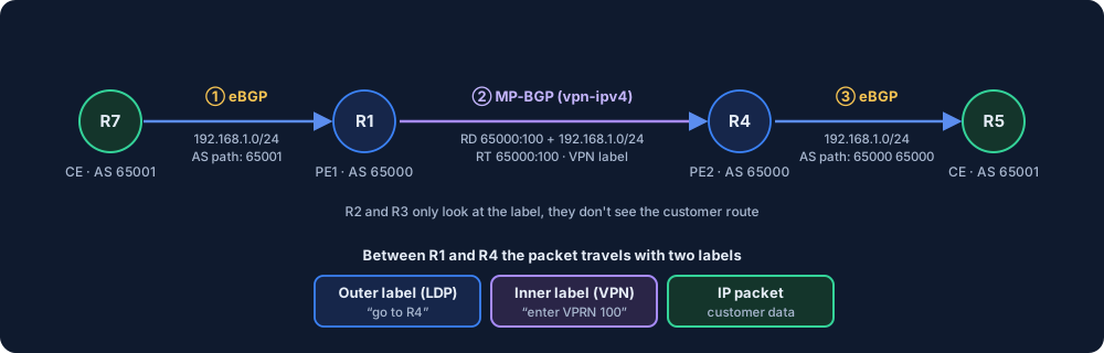
The route travels along a three-part path:
- CE → PE (eBGP): The CE tells the PE about its LAN. This session is set up inside the customer’s VRF.
- PE → PE (MP-BGP,
vpn-ipv4): The PE labels this route and carries it to the remote PE. The P routers in between never see the customer route, they only look at the MPLS label. - PE → CE (eBGP): The remote PE takes the route into its own VRF and gives it to its own CE.
The path that carries the packet is two-layered: the outer label is the “go to the remote PE” label from LDP, the inner label is the “which VPRN will you enter” label.
3. Topology and IP plan
A single customer (A), two sites. There are two P routers between the PEs.
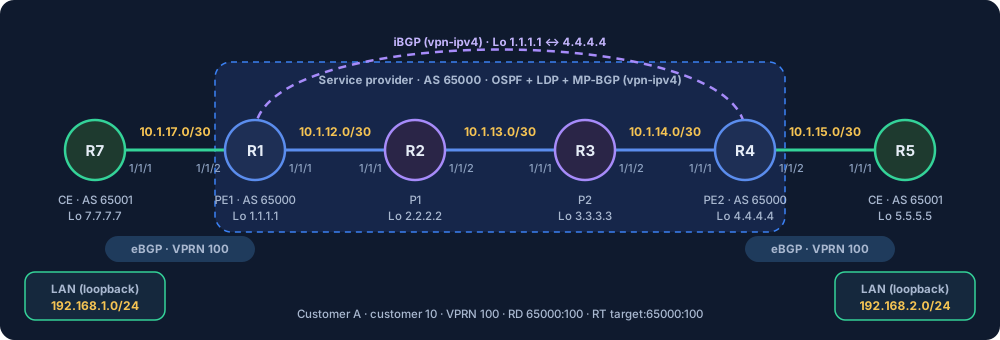
| Device | Role | System IP | Connections |
|---|---|---|---|
| R7 | CE (site 1) | 7.7.7.7 | to the PE 10.1.17.0/30 (R7: .2) · LAN 192.168.1.0/24 |
| R1 | PE1 | 1.1.1.1 | R7: 10.1.17.1 (1/1/2) · R2: 10.1.12.1 (1/1/1) |
| R2 | P1 | 2.2.2.2 | R1: 10.1.12.2 · R3: 10.1.13.1 |
| R3 | P2 | 3.3.3.3 | R2: 10.1.13.2 · R4: 10.1.14.1 |
| R4 | PE2 | 4.4.4.4 | R3: 10.1.14.2 (1/1/1) · R5: 10.1.15.1 (1/1/2) |
| R5 | CE (site 2) | 5.5.5.5 | to the PE 10.1.15.0/30 (R5: .2) · LAN 192.168.2.0/24 |
Service details:
| Value | |
|---|---|
| Service provider AS | 65000 |
| Customer AS (both sites) | 65001 |
| Customer ID | 10 |
| VPRN ID | 100 |
| RD | 65000:100 |
RT (vrf-target) | target:65000:100 |
Putting the two sites in the same AS is something I chose on purpose. In real life customers usually use a single AS at all their sites, and this creates the classic trap you’ll see below.
4. The core: preparation
The core is like in the previous posts: OSPF, LDP and MP-BGP between the PEs. Here I’ll just leave two notes.
OSPF interface type. On Nokia, an OSPF interface comes up as broadcast by default. On a point-to-point link between two routers there’s no need for this: you wait for the DR/BDR election (~40 s on a real device), and a Type-2 LSA is also generated. Write interface-type point-to-point on the core links. It must be the same on both ends, if one stays broadcast and the other p2p, the neighborship doesn’t come up.
configure router ospf area 0.0.0.0 interface "toP1" interface-type point-to-point
LDP. Don’t put LDP on the PE–CE interfaces. Only the core links (on R1 the one facing R2, on R2 both sides, on R3 both sides, on R4 the one facing R3) should be in LDP.
MP-BGP between the PEs (on R1; on R4 the router-id and local-address become 4.4.4.4 and neighbor 1.1.1.1):
configure router autonomous-system 65000
configure router bgp
    router-id 1.1.1.1
    group "iBGP"
        peer-as 65000
        local-address 1.1.1.1
        family vpn-ipv4
        neighbor 4.4.4.4
        exit
    exit
    no shutdown
exit all
Check: show router bgp summary should show the neighbor as Established. Without the family vpn-ipv4 line the session comes up, but VPRN routes aren’t carried.
5. The VPRN service (on the PEs)
First the customer and the port. The port facing the CE has to be in access mode, and you need to shut down the port before changing the mode:
configure port 1/1/2 shutdown
configure port 1/1/2 ethernet mode access
configure port 1/1/2 no shutdown
configure service customer 10 create
    description "Musteri-A"
exit all
Then the VPRN (on R1; on R4 port 1/1/2 and address 10.1.15.1/30):
configure service vprn 100 customer 10 create
    route-distinguisher 65000:100
    vrf-target target:65000:100
    auto-bind-tunnel
        resolution any
    exit
    interface "toR7" create
        address 10.1.17.1/30
        sap 1/1/2 create
        exit
    exit
    no shutdown
exit all
The lines:
customer 10: The owner of the service. This number only has meaning inside the PE, it isn’t carried in BGP. It doesn’t have to be the same on R1 and R4. But don’t use1: that’s the default customer in SR OS.route-distinguisher: The tag added to the front of the VPN-IPv4 route. It separates two customers in BGP even if they use the same prefix. It doesn’t decide who the route goes to. In real networks, giving a separate RD to each PE is good practice (1.1.1.1:100,4.4.4.4:100): once a route reflector comes in between, two paths with the same RD can be counted as a single route and you can lose one of them. In this lab I used65000:100on both PEs, and since there’s a single customer and no RR, it caused no problem.vrf-target: The RT. It makes the “which route goes into which VRF” decision. It must be the same on both PEs: this is what ties the two ends of the VPN together.auto-bind-tunnel/resolution any: Tells the PE “which MPLS tunnel you may use when going to the VPN route’s next hop”. If you don’t write it, the VPRN can’t resolve the route it learned from the remote PE and doesn’t take it into the VRF. I forgot this once, see below.interface ... sap: The PE–CE connection is defined inside the VPRN, not in the global router. I got this wrong once too.
6. The CE side: AS, LAN and policy
On R7, first the AS and the LAN. Instead of tying the LAN to a real interface, I defined it as a loopback (there are no hosts on the LAN side in the simulation):
configure router autonomous-system 65001
configure router interface "LAN" address 192.168.1.1/24
configure router interface "LAN" loopback
What is interface "LAN" loopback for? At a real site there would be a switch and computers behind the CE. In the simulation there are no hosts there, but we need a LAN network to give to BGP. An interface defined as loopback is a virtual interface that isn’t tied to any port and is always “up”. When you give it 192.168.1.1/24, the router counts this network as its own directly connected network and answers pings: an imitation of “there’s a LAN behind the CE”. That’s also why protocol direct in the policy catches it.
Before getting to the policy part, let’s make one thing clear.
6.1. Why do we write a policy?
If you opened the BGP neighborship on the CE but didn’t write anything else, R7 sends no routes to the PE. In SR OS, BGP by default only distributes routes it learned from BGP. The LAN on its own interface (this is called direct) doesn’t enter BGP by itself. There’s no equivalent of Cisco’s network command, you write explicitly what to give.
This is an export policy job: “send these routes when going to the BGP neighbor.”
6.2. The policy line by line
configure router policy-options
    begin
    prefix-list "LAN"
        prefix 192.168.1.0/24 exact
    exit
    policy-statement "EXPORT-LAN"
        entry 10
            from
                protocol direct
                prefix-list "LAN"
            exit
            action accept
            exit
        exit
    exit
    commit
exit all
configure router bgp group "PE" export "EXPORT-LAN"
| Line | What it does |
|---|---|
policy-options | The router’s “rule book”. You define here what BGP will give and take. |
begin | Starts the change. What you write after this is a draft, it isn’t active. |
prefix-list "LAN" | A list named “LAN”. It doesn’t do anything on its own, it’s just a group of prefixes. |
prefix 192.168.1.0/24 exact | Adds a network to the list. exact means “exactly this network”: wider or narrower ones don’t count. |
policy-statement "EXPORT-LAN" | The name of the rule set. You’ll tie this to BGP later. |
entry 10 | An item of the rule. If there are several, the smaller number is checked first. |
from | The conditions. What you write under it is joined with and (all must be true at once). |
protocol direct | “If the route came from a directly connected interface.” It states the source type. On real SR OS, if you don’t write the source at all, the entry can match any source, but writing it explicitly makes the intent clear and prevents routes learned from BGP from going out by mistake. In the simulator the LAN wasn’t given without this line, so we write it. |
prefix-list "LAN" | “And if the route is in the LAN list.” |
action accept | If it matches, accept: that is, send it to the neighbor. If you don’t write this, there are conditions but nothing to do, and the rule does nothing. |
commit | Makes the draft active. If you don’t write it, nothing has changed. |
export "EXPORT-LAN" | Ties the policy to the BGP group. Writing a policy and not tying it is a very common mistake. |
Look at how three different routes pass through this policy. Only the LAN meets all three conditions:
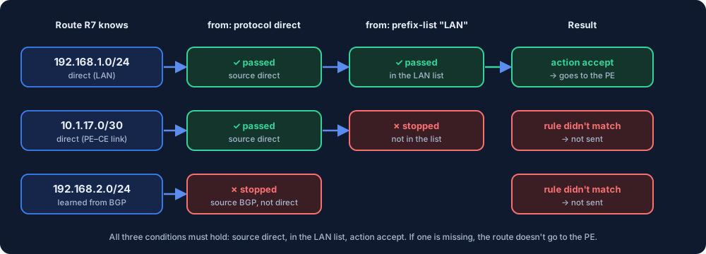
A tip: after writing the begin…commit block, look with info at whether the prefix shows up inside the prefix-list and action accept shows up inside the entry. If they’re empty, either an exit was written one too many or too few, or a line was swallowed. I went through this below.
6.2.1. For later: is a policy needed on the PE side too?
On a real device, a policy may also be needed for eBGP on the PE side. According to Nokia’s documentation, in classic CLI the default for eBGP is to take and give all routes without a policy. In MD-CLI the default follows RFC 8212: if there’s no policy, no routes are taken from or given to the eBGP neighbor. Configurations converted from classic keep the old behavior. If you want, you can force this in classic too:
configure service vprn 100 bgp group "CE" ebgp-default-reject-policy import export
The setup in this post works with classic CLI and the default behavior. The simulator doesn’t model this default reject behavior, so routes flow there even without writing a policy on the PE. On a device using MD-CLI, you need to write import and export policies on the PE too. (Nokia: EBGP Default Reject Policy, RFC 8212)
6.3. BGP on the CE
configure router bgp
    group "PE"
        peer-as 65000
        export "EXPORT-LAN"
        neighbor 10.1.17.1
        exit
    exit
    no shutdown
exit all
The same on R5: LAN 192.168.2.1/24, 192.168.2.0/24 in the prefix-list, neighbor 10.1.15.1.
7. The PE side: eBGP inside the VPRN
On the PE, the CE neighbor is defined inside the VPRN. The global router bgp is only for MP-BGP between the PEs:
configure service vprn 100
    bgp
        group "CE"
            peer-as 65001
            as-override
            neighbor 10.1.17.2
            exit
        exit
        no shutdown
    exit
exit all
On R4 the neighbor is 10.1.15.2. as-override makes the PE do this: when giving the route to the CE, it replaces the customer AS in the AS path with its own AS (65000). You’ll see why it’s needed in 9.5: in short, if both sites are in the same AS, the CE sees its own AS in the other site’s route, thinks it’s a loop and rejects the route, and as-override prevents this.
Why is the neighbor the interface IP, not the loopback? There’s a single cable between PE and CE, and that cable’s IPs (10.1.17.1 ↔ 10.1.17.2) are solid enough as neighbors. eBGP packets go out with TTL 1 by default, so they can only go one step away; that’s enough for a directly connected neighbor. If you wanted to set it up with loopbacks, you’d need two things: a route on both sides to each other’s loopback (static or IGP) and multihop in eBGP. With a single link there’s no gain, it just adds work. The value of a loopback shows up when there’s more than one path: even if one of the links breaks, the session doesn’t drop thanks to the other path to the loopback. That’s why we use the loopback in iBGP between the PEs: there are R2 and R3 between them, the path can change, but the loopback always stays reachable.
Check:
show router 100 bgp summary
If you see 1/1/... in the Rcv/Act/Sent column for the neighbor, the CE’s LAN has reached the PE. If it’s 0/0/0, the session is up but the CE isn’t sending anything: look at the policy.
8. Verification
show router 100 route-table
show router bgp routes vpn-ipv4
ping 192.168.2.1 source 192.168.1.1
- On R1,
192.168.2.0/24should show up as BGP VPN, with next hop4.4.4.4 (tunneled).
- The
pingshould be sent from R7 with the LAN source:source 192.168.1.1. If you don’t give a source, the packet goes out with the PE–CE interface’s address, and the remote CE’s return path may be different.
9. Where I got stuck
While doing this setup from scratch I got stuck in four places, and the fifth is a classic trap. I’m writing them all in the same order, because knowing the symptoms is what saves the most time.
9.1. Rcv = 0 on the PE: the policy was empty
Symptom: On the PE, show router 100 bgp summary shows the neighbor, the session is up, but it’s 0/0/0. On the CE, show router bgp neighbor 10.1.17.1 advertised-routes says “No Matching Entries Found”.
Cause: I had written the policy, but when I looked with info, the inside of prefix-list "LAN" was empty and there was no action accept under entry 10. The policy wasn’t accepting anything.
Fix: I rewrote it from the start with begin and did commit. The result should look like this in info:
prefix-list "LAN"
    prefix 192.168.1.0/24 exact
exit
policy-statement "EXPORT-LAN"
    entry 10
        from
            prefix-list "LAN"
        exit
        action accept
        exit
    exit
exit
9.2. The policy is right but still empty: protocol direct was missing
Symptom: The prefix-list is filled, action accept is there, commit was done, and still advertised-routes is empty.
Cause: I hadn’t written the source type under from in the policy. R7 didn’t learn the LAN from BGP, it knows it from its own interface (direct). In the simulator the rule didn’t match this source.
Fix: I added protocol direct under from. In the first advertised-routes output 192.168.1.0/24 showed up, and Rcv on the PE became 1.
9.3. No ping: “LSP yok” (no LSP) on the map
Symptom: The BGPs are Established, there are VPN routes on the PEs, but the ping from R7 doesn’t go through. On the simulator’s map, a red label between the PEs: LSP yok (no LSP).
Cause: I had forgotten to write auto-bind-tunnel in the VPRN. The PE learns the route from the remote PE, but since it doesn’t have the information “which MPLS tunnel will I take to this next hop”, it can’t take the route into the VRF and use it.
Fix: I added auto-bind-tunnel + resolution any to the VPRN on both PEs. The tunnel itself (LDP) was ready in the core, to check:
show router ldp session          (neighbors Established)
show router tunnel-table         (4.4.4.4/32 on R1, 1.1.1.1/32 on R4, owner: ldp)
If the remote PE isn’t in the tunnel-table, the problem is in LDP (LDP missing on the core links); if it’s there and the ping still doesn’t work, look at auto-bind-tunnel.
9.4. Double interface: the same IP and port both in global and in the VPRN
Symptom: This is the most interesting one. R1 can ping its own CE (ping router 100 10.1.17.2) and R4 can ping its own CE. R1 and R4 can ping each other (inside the VPRN, ping router 100 10.1.15.1). But traffic coming from the tunnel doesn’t pass to the other side’s CE: the ping from R1 to R5’s LAN and from R4 to R7’s LAN times out.
Cause: I saw it when I looked at admin display-config: I had defined the PE–CE connection both in the global router (interface "toCER7" address 10.1.17.1/30 port 1/1/2) and in the VPRN (interface "toR7" ... sap 1/1/2). While writing the core I had also added the PE–CE interface to global, then created it again in the VPRN. The same IP, the same port, in two separate routing instances. The packet gets confused about which one it belongs to.
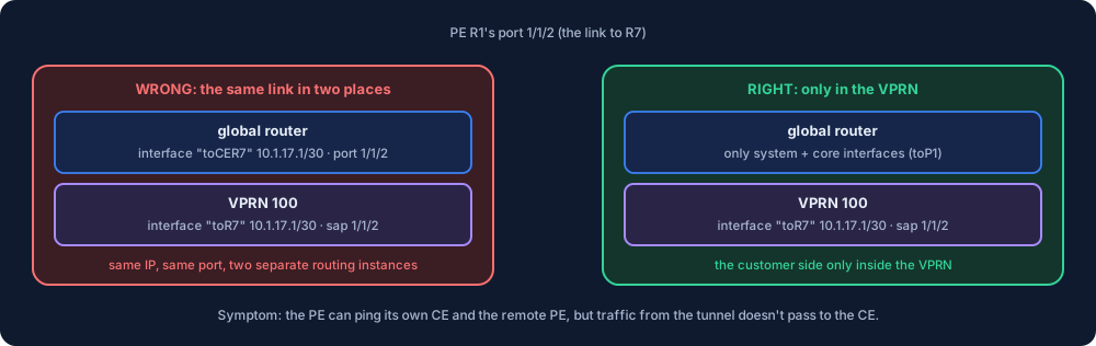
Fix: I deleted the copies in global:
configure router
    interface "toCER7" shutdown
    no interface "toCER7"
exit all
On R4 it’s toCER5. The interfaces facing the customer side are only inside the VPRN. In the global router, the PE has only the core interfaces and system.
The way to find it was narrowing it down with pings: it goes to my own CE, it goes to the remote PE, but it doesn’t go to the remote CE. If it breaks at the same point in both directions, you need to look at the configuration; admin display-config showed the same IP appearing in two places.
9.5. The AS loop: the remote LAN doesn’t arrive
This is the classic trap of PE–CE eBGP. Since I wrote as-override from the start, I didn’t hit it in the setup, but you need to know why. If you want to try it, remove as-override on the PEs (no as-override) and look at the CEs’ tables: the other site doesn’t show up.
Cause: When R7’s 192.168.1.0/24 goes PE1 → PE2 → R5, the AS path becomes: the PE’s AS (65000) and the customer’s AS (65001). When R5 receives the route, it sees its own AS (65001) in the path, and eBGP’s loop protection rejects the route: “this route has come back to me”. Since both sites are in the same AS, they can never learn the other site’s route.
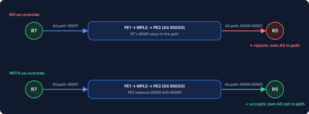
Fixes (both work):
as-overrideon the PE: When giving the route to the CE, the PE replaces the customer AS in the path with its own AS. The path becomes “65000 65000”, and the CE accepts it. You write it once on the PE, and it applies to all sites.allow-as-loopon the CE: The CE doesn’t reject when it sees its own AS in the path. You need to write it on every CE separately.
I prefer as-override: you don’t touch the customer’s routers.
10. The dynamic side of the route
With a static route, if a site goes down the route stays on the PE, and the traffic disappears into a black hole. In BGP, when the CE withdraws its LAN (when you remove the policy or shut down the interface), the route is deleted on its own, first from R1’s VRF, then from R4 over VPN-IPv4, and finally from R5’s table. To try it, on R7:
configure router bgp group "PE" no export
type this, look at show router route-table on R5, and the route will be gone. To tie it back, export "EXPORT-LAN".
11. Summary
- PE–CE eBGP is set up inside the VPRN (
configure service vprn 100 bgp); the global BGP is only between the PEs. - Turning on BGP on the CE isn’t enough: to give the LAN, an export policy is required:
prefix-list+policy-statement(from protocol direct,prefix-list,action accept) +exporton the group +commit. - If both sites are in the same AS,
as-overrideon the PE orallow-as-loopon the CE is needed. - For the VPN route, LDP in the core and
auto-bind-tunnelin the VPRN are required. - The PE–CE interface is defined only in the VPRN, not in the global router.
- The RD is for uniqueness, the RT (
vrf-target) decides which VRF the route goes into.
You can also find the topology from this post ready-made on the Simulation page (Turkish UI): Yeni → Nokia → “PE–CE eBGP: tek müşteri, iki site” (one customer, two sites). “Konfigle aç” (open with config) brings customer A fully set up. Customer B’s (R8 and R6) cables are ready but the configuration is empty: you can reinforce the steps in the post by setting up VPRN 200 yourself. With “Sadece topoloji” (topology only) you can also write everything from scratch.
Try the same setup in your own browser: PE–CE eBGP lab (Turkish). The core comes ready, you set up BGP and the policy on the CE, and the in-VRF neighbor and as-override on the PE.
The Huawei VRP equivalent of the same job (substitute-as, export without a policy, the neighbor inside the VPN instance) is in the Huawei PE–CE eBGP post, with the differences from Nokia in a table.