1. Topology and Goal
There are very few Turkish resources on Nokia SR OS, so I’m writing down what I learn in the lab. In this post we build a simple MPLS core and show two things:
- How do an IGP and LDP work together? OSPF teaches the loopbacks to each other, and LDP puts labels on top of those routes to build an LSP (transport tunnel) between the PEs.
- What is the label for? Inside the core, the packet moves by label, not by IP lookup. We’ll see step by step where the label is attached (push), where it is changed (swap) and where it is removed (pop).
Cargo analogy
Think of IP routing as reading the address on a parcel at every sorting hub and asking “where was this going?”. In MPLS, a barcode is stuck on the parcel at the first hub. The hubs in between don’t read the address, they just look at the barcode and steer the belt. LDP is the protocol where neighboring hubs tell each other “this barcode goes to this address”.
Topology
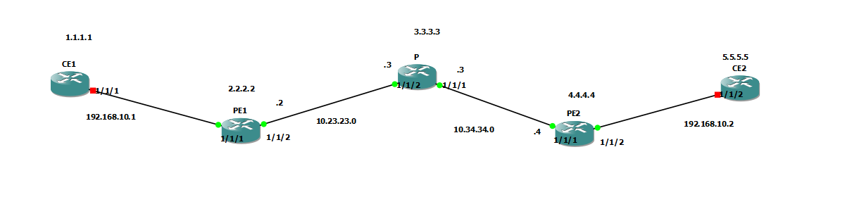
| Device | Role | Loopback (System) |
|---|---|---|
| CE1 | Customer edge | 1.1.1.1 |
| PE1 | Provider Edge | 2.2.2.2 |
| P | Provider (core) | 3.3.3.3 |
| PE2 | Provider Edge | 4.4.4.4 |
| CE2 | Customer edge | 5.5.5.5 |
| Link | Subnet | Interfaces |
|---|---|---|
| CE1 - PE1 | 192.168.10.0/24 | CE1 1/1/1 (.1) - PE1 1/1/1 |
| PE1 - P | 10.23.23.0/24 | PE1 1/1/2 (.2) - P 1/1/2 (.3) |
| P - PE2 | 10.34.34.0/24 | P 1/1/1 (.3) - PE2 1/1/1 (.4) |
| PE2 - CE2 | 192.168.10.0/24 | PE2 1/1/2 - CE2 1/1/2 (.2) |
On the provider side (PE1, P, PE2) the IGP is OSPF. Our goal is to build an LSP with LDP between PE1 (2.2.2.2) and PE2 (4.4.4.4).
2. Starting Point: OSPF and Loopback Reachability
LDP has no path-finding ability of its own. When it distributes labels it looks at the routes built by the IGP: it gets the answer to “who is the next hop for this prefix?” from the routing table. So the IGP has to work properly first. Here all three routers run OSPF in a single area (0.0.0.0).
OSPF configuration
The structure is the same on all three routers: a single area (0.0.0.0), the system interface (to advertise the loopback) and the core-facing interfaces. We made the links point-to-point, so there is no DR/BDR election and the adjacency comes up faster.
PE1
A:PE1-R2>config>router>ospf# info
----------------------------------------------
            area 0.0.0.0
                interface "system"
                    no shutdown
                exit
                interface "toP"
                    interface-type point-to-point
                    no shutdown
                exit
            exit
            no shutdown
----------------------------------------------
P
A:P-R3>config>router>ospf# info
----------------------------------------------
            area 0.0.0.0
                interface "system"
                    no shutdown
                exit
                interface "toPE1"
                    interface-type point-to-point
                    no shutdown
                exit
                interface "toPE2"
                    interface-type point-to-point
                    no shutdown
                exit
            exit
            no shutdown
PE2
A:PE2-R4>config>router>ospf# info
----------------------------------------------
            area 0.0.0.0
                interface "system"
                    no shutdown
                exit
                interface "toP"
                    interface-type point-to-point
                    no shutdown
                exit
            exit
            no shutdown
We did not add the CE-facing interfaces (PE1 1/1/1, PE2 1/1/2) to OSPF. The customer side stays out of the provider IGP.
OSPF neighbors
All adjacencies on PE1, P and PE2 are in the Full state:
A:PE1-R2# show router ospf neighbor

===============================================================================
Rtr Base OSPFv2 Instance 0 Neighbors
===============================================================================
Interface-Name                   Rtr Id          State      Pri  RetxQ   TTL
   Area-Id
-------------------------------------------------------------------------------
toP                              3.3.3.3         Full       1    0       31
   0.0.0.0
-------------------------------------------------------------------------------
No. of Neighbors: 1
===============================================================================
A:P-R3# show router ospf neighbor

===============================================================================
Rtr Base OSPFv2 Instance 0 Neighbors
===============================================================================
Interface-Name                   Rtr Id          State      Pri  RetxQ   TTL
   Area-Id
-------------------------------------------------------------------------------
toPE1                            2.2.2.2         Full       1    0       33
   0.0.0.0
toPE2                            4.4.4.4         Full       1    0       36
   0.0.0.0
-------------------------------------------------------------------------------
No. of Neighbors: 2
A:PE2-R4# show router ospf neighbor

===============================================================================
Rtr Base OSPFv2 Instance 0 Neighbors
===============================================================================
Interface-Name                   Rtr Id          State      Pri  RetxQ   TTL
   Area-Id
-------------------------------------------------------------------------------
toP                              3.3.3.3         Full       1    0       35
   0.0.0.0
-------------------------------------------------------------------------------
No. of Neighbors: 1
Since P sits in the middle it has two neighbors (PE1 and PE2), while each edge PE has just one.
Route table
Let’s look at PE1’s route table:
A:PE1-R2# show router route-table

===============================================================================
Route Table (Router: Base)
===============================================================================
Dest Prefix[Flags]                            Type    Proto     Age        Pref
      Next Hop[Interface Name]                                    Metric
-------------------------------------------------------------------------------
2.2.2.2/32                                    Local   Local     00h01m45s  0
       system                                                       0
3.3.3.3/32                                    Remote  OSPF      00h00m51s  10
       10.23.23.3                                                   100
4.4.4.4/32                                    Remote  OSPF      00h00m31s  10
       10.23.23.3                                                   200
10.23.23.0/24                                 Local   Local     00h00m55s  0
       toP                                                          0
10.34.34.0/24                                 Remote  OSPF      00h00m51s  10
       10.23.23.3                                                   200
-------------------------------------------------------------------------------
No. of Routes: 5
Pay attention here: PE1 learned PE2’s loopback (4.4.4.4/32) via OSPF, the next hop is 10.23.23.3 (the P router) and the metric is 200 (two hops, 100 per hop). The FECs LDP will distribute labels for are exactly these loopback prefixes.
But at this point we have IP reachability and no MPLS yet. A packet from PE1 to 4.4.4.4 is forwarded at P with a normal IP lookup. In the next section we’ll turn LDP on and see how labels get layered on top of this table.
3. LDP Configuration
The LDP configuration is actually very short. All we have to do is enable LDP on the router and tell it which interfaces to look for neighbors on. We only add the core-facing interfaces, we don’t enable LDP on the CE-facing ones. There is no point in giving labels to the customer.
When establishing a session, LDP uses the system (loopback) address by default. That means the two routers must be able to reach each other’s loopbacks. We made sure of this with OSPF in the previous section, and this is exactly why LDP needs an IGP.
When LDP is enabled, the router creates every interface under interface-parameters as dual-stack. In the output we see the ipv4 block and the IPv6 FECs disabled (disable) under fec-type-capability. We only use IPv4, so this part doesn’t concern us. The targeted-session block at the bottom is for remote (loopback-to-loopback) LDP sessions, which we’ll need on the service side.
PE1
A:PE1-R2>config>router>ldp# info
----------------------------------------------
            interface-parameters
                interface "toP" dual-stack
                    ipv4
                        fec-type-capability
                            prefix-ipv6 disable
                            p2mp-ipv6 disable
                        exit
                        no shutdown
                    exit
                    no shutdown
                exit
            exit
            targeted-session
            exit
            no shutdown
----------------------------------------------
P
A:P-R3>config>router>ldp# info
----------------------------------------------
            interface-parameters
                interface "toPE1" dual-stack
                    ipv4
                        fec-type-capability
                            prefix-ipv6 disable
                            p2mp-ipv6 disable
                        exit
                        no shutdown
                    exit
                    no shutdown
                exit
                interface "toPE2" dual-stack
                    ipv4
                        fec-type-capability
                            prefix-ipv6 disable
                            p2mp-ipv6 disable
                        exit
                        no shutdown
                    exit
                    no shutdown
                exit
            exit
            targeted-session
            exit
            no shutdown
----------------------------------------------
PE2
A:PE2-R4>config>router>ldp# info
----------------------------------------------
            interface-parameters
                interface "toP" dual-stack
                    ipv4
                        fec-type-capability
                            prefix-ipv6 disable
                            p2mp-ipv6 disable
                        exit
                        no shutdown
                    exit
                    no shutdown
                exit
            exit
            targeted-session
            exit
            no shutdown
----------------------------------------------
In short, we did two things on each router: enabled LDP with no shutdown and added the core-facing interfaces under interface-parameters. That’s one interface on the PEs and two on P.
4. Verifying LDP
The configuration is done. Now we verify that LDP is really working in three steps: neighbor discovery (hello adjacency), label distribution (bindings) and the resulting tunnel (tunnel-table). I’m taking the outputs from PE1.
Hello adjacency
LDP first finds its neighbor by sending hello packets out of the connected interfaces. The Estab state shows that PE1 has established its adjacency with P:
A:PE1-R2# show router ldp discovery

===============================================================================
LDP IPv4 Hello Adjacencies
===============================================================================
Interface Name                   Local Addr                              State
AdjType                          Peer Addr
-------------------------------------------------------------------------------
toP                              2.2.2.2:0                               Estab
link                             3.3.3.3:0

-------------------------------------------------------------------------------
No. of IPv4 Hello Adjacencies: 1
===============================================================================
AdjType is link, a directly connected adjacency. The neighbor’s address is 3.3.3.3:0, so the LDP session is established with P’s loopback address. (The IPv6 adjacency table is empty because we only use IPv4.)
Label bindings
After the adjacency, the routers send each other “use this label for this prefix”. The IPv4 prefix bindings on PE1:
A:PE1-R2# show router ldp bindings

===============================================================================
LDP IPv4 Prefix Bindings
===============================================================================
Prefix                                      IngLbl                    EgrLbl
Peer                                        EgrIntf/LspId
EgrNextHop
-------------------------------------------------------------------------------
2.2.2.2/32                                  131071U                     --
3.3.3.3:0                                     --
  --

3.3.3.3/32                                    --                      131071
3.3.3.3:0                                   1/1/2
10.23.23.3

4.4.4.4/32                                  131069N                   131069
3.3.3.3:0                                   1/1/2
10.23.23.3

-------------------------------------------------------------------------------
No. of IPv4 Prefix Bindings: 3
===============================================================================
The real output also has IPv6, P2MP and service FEC tables. All of them say
No Matching Entries Found, so I cut them here.
How to read the columns:
- IngLbl (ingress label): The label this router gives to its neighbor: “if you want to reach this prefix, come to me with this label”.
- EgrLbl (egress label): The label the neighbor gives to this router: “send to me with this label for this prefix”.
- U / N:
Umeans the label is in use,Nmeans not in use.
131071 is a special value here: implicit null. It means “this prefix is mine, pop the label and send it”. PE1 gave 131071 to P for its own loopback (2.2.2.2/32). P gave PE1 131071 for its own loopback (3.3.3.3/32). We’ll see why this matters in section 5.
The egress label PE1 will use for 4.4.4.4/32 is 131069, given by P.
Tunnel table
Once the labels are distributed, LDP creates a tunnel for each FEC and writes it into the tunnel-table:
A:PE1-R2# show router tunnel-table

===============================================================================
IPv4 Tunnel Table (Router: Base)
===============================================================================
Destination       Owner     Encap TunnelId  Pref     Nexthop        Metric
-------------------------------------------------------------------------------
3.3.3.3/32        ldp       MPLS  65537     9        10.23.23.3     100
4.4.4.4/32        ldp       MPLS  65538     9        10.23.23.3     200
-------------------------------------------------------------------------------
Flags: B = BGP backup route available
       E = inactive best-external BGP route
===============================================================================
Here is what we were looking for: there is an LDP LSP from PE1 to PE2’s loopback (4.4.4.4/32). Owner ldp, encapsulation MPLS, next hop P. OSPF decides the path of this tunnel (the metric is still 200), and LDP puts the label on it. So the IGP picks the path, LDP distributes labels along it.
5. Push / Swap / Pop
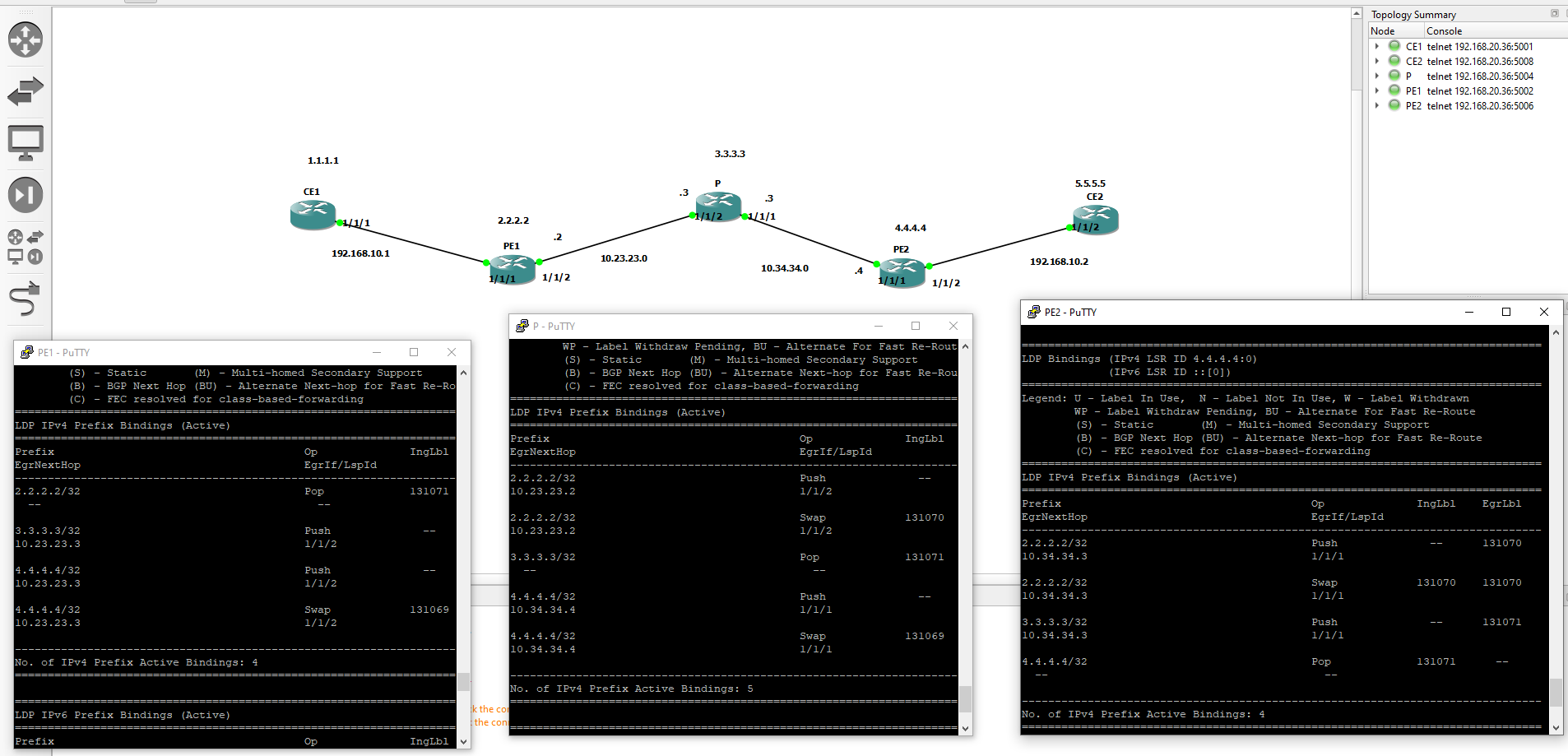
Now we look at what the label does hop by hop. For that we list the active bindings (the ones installed in the FIB and in use) on the three routers:
show router ldp bindings active
In the output, the Op column tells us what that router does with the label.
Three operations
| Operation | What it does | Cargo analogy |
|---|---|---|
| Push | Adds a label to the packet | Sticking a barcode on the parcel at the departure hub |
| Swap | Replaces the incoming label with the label given by the next router | Peeling off the old barcode at an intermediate hub and sticking the new one the next hub will read |
| Pop | Removes the label | Removing the barcode at the delivery hub and delivering by the address |
Key point: these operations are done for the LSP between the PEs. Only the ingress PE puts the label on the packet. The P router in the middle (transit) doesn’t look at the IP address, it only looks at the label and swaps it. The egress side removes the label.
Active binding outputs
PE1
A:PE1-R2# show router ldp bindings active

LDP IPv4 Prefix Bindings (Active)
===============================================================================
Prefix                                      Op              IngLbl    EgrLbl
EgrNextHop                                  EgrIf/LspId
-------------------------------------------------------------------------------
2.2.2.2/32                                  Pop             131071      --
  --                                          --

3.3.3.3/32                                  Push              --      131071
10.23.23.3                                  1/1/2

4.4.4.4/32                                  Push              --      131069
10.23.23.3                                  1/1/2

4.4.4.4/32                                  Swap            131069    131069
10.23.23.3                                  1/1/2

-------------------------------------------------------------------------------
P
A:P-R3# show router ldp bindings active

LDP IPv4 Prefix Bindings (Active)
===============================================================================
Prefix                                      Op              IngLbl    EgrLbl
EgrNextHop                                  EgrIf/LspId
-------------------------------------------------------------------------------
2.2.2.2/32                                  Push              --      131071
10.23.23.2                                  1/1/2

2.2.2.2/32                                  Swap            131070    131071
10.23.23.2                                  1/1/2

3.3.3.3/32                                  Pop             131071      --
  --                                          --

4.4.4.4/32                                  Push              --      131071
10.34.34.4                                  1/1/1

4.4.4.4/32                                  Swap            131069    131071
10.34.34.4                                  1/1/1

-------------------------------------------------------------------------------
PE2
A:PE2-R4# show router ldp bindings active

LDP IPv4 Prefix Bindings (Active)
===============================================================================
Prefix                                      Op              IngLbl    EgrLbl
EgrNextHop                                  EgrIf/LspId
-------------------------------------------------------------------------------
2.2.2.2/32                                  Push              --      131070
10.34.34.3                                  1/1/1

2.2.2.2/32                                  Swap            131070    131070
10.34.34.3                                  1/1/1

3.3.3.3/32                                  Push              --      131071
10.34.34.3                                  1/1/1

4.4.4.4/32                                  Pop             131071      --
  --                                          --

-------------------------------------------------------------------------------
If you want to see the outputs of all three routers side by side on the GNS3 screen:
The path from PE1 to PE2 (4.4.4.4/32)
Let’s trace the path from PE1 to PE2’s loopback (4.4.4.4/32) step by step from the outputs:
| Step | Router | Operation | Label |
|---|---|---|---|
| 1 | PE1 (ingress) | Push | 131069 is put on the packet, it goes to P via 1/1/2 |
| 2 | P (transit) | Swap | The incoming 131069 is replaced, the outgoing label is 131071 (implicit null), it goes to PE2 via 1/1/1 |
| 3 | PE2 (egress) | Pop | 4.4.4.4/32 is PE2’s own address, the label is already 131071, the packet is processed as plain IP |
The reverse direction: PE2 to PE1 (2.2.2.2/32)
When the direction is reversed, the same logic applies:
| Step | Router | Operation | Label |
|---|---|---|---|
| 1 | PE2 (ingress) | Push | 131070 is put on, it goes to P via 1/1/1 |
| 2 | P (transit) | Swap | 131070 → 131071 (implicit null), it goes to PE1 via 1/1/2 |
| 3 | PE1 (egress) | Pop | 2.2.2.2/32 is PE1 itself |
Implicit null and PHP
There is something notable in the P line above: the egress label is 131071. That is implicit null. P doesn’t replace the label with a real value, it removes it and sends a plain IP packet to PE2. This is called PHP (Penultimate Hop Popping), meaning the label is removed at the second-to-last hop.
Why is it done this way? If PE2 removed the label, it would first have to look at the label and then do an IP lookup as well. When the label is removed at P, PE2 only does an IP lookup, one job less.
In practice: if you capture a packet on the link between P and PE2 (10.34.34.0/24), you won’t see a label on it. On the link between PE1 and P you will see the label 131069. The label is only carried on the first leg of this LSP.
If we look at the other FECs (for example PE1’s 3.3.3.3/32 line), it’s the same there: the label P gives for its own loopback is 131071, so PE1 sends to P without adding a label (Push + implicit null), and it shows up as Pop on P.
The extra
Swaplines on PE1 and PE2 (e.g. 131069 → 131069 for 4.4.4.4/32 on PE1) are not part of this flow. When reading the table it’s enough to focus onPush, theSwapon P and thePopon the destination PE.
6. Summary
- OSPF taught the PEs’ loopbacks to each other and decided the path.
- LDP distributed labels over these routes and built an LSP between PE1 and PE2 (
show router tunnel-table). - The ingress PE does push, the P router does swap, the egress side does pop. Thanks to implicit null, the label is actually removed at P (PHP).
- The P router forwards using only the label, without looking at the packet’s IP address. That is the gain MPLS provides in the core.
In the next post we’ll build a service (Epipe/VPLS) on top of this LSP and connect CE1 with CE2.