I had earlier set up a VPRN on Nokia SR OS. In this post I set up the same service on Huawei VRP, on an AR2200 router in eNSP. The logic is the same: OSPF + LDP in the backbone, a customer-specific routing table on the PEs, MP-BGP between the PEs. What changes is the language of the commands. So first I collected the equivalents of the two vendors in a single table, then I wrote the setup step by step.
Nokia and Huawei command comparison
| What we’re doing | Nokia SR OS | Huawei VRP |
|---|---|---|
| Turning on LDP | configure router ldp + interface-parameters interface "to-P" create | mpls lsr-id 1.1.1.1 → mpls → mpls ldp (global), then mpls + mpls ldp on the interface |
| LSR identity | system IP (loopback), automatic | given by hand with mpls lsr-id |
| Customer definition | service customer 10 create | none (not a separate concept) |
| Creating the VRF | service vprn 300 customer 10 create | ip vpn-instance VPRN_SERVICE → ipv4-family |
| RD | route-distinguisher 65200:300 | route-distinguisher 65000:100 (under ipv4-family) |
| RT | vrf-target target:65200:300 | vpn-target 65000:100 both |
| Putting the interface into the VRF | interface "x" create + sap 1/1/1 create inside the VPRN | ip binding vpn-instance VPRN_SERVICE on the physical interface (before the IP) |
| Transport tunnel | auto-bind-tunnel resolution-filter ldp (stated explicitly) | no need to write it, the default tunnel is the LDP LSP |
| MP-BGP family | family vpn-ipv4 | ipv4-family vpnv4 + peer ... enable |
| BGP source address | local-address 2.2.2.2 | connect-interface LoopBack0 |
| iBGP preference | 170 | 255 |
| OSPF preference | 10 | 10 |
| Static preference | 5 | 60 |
| Saving | admin save | save (in user view, <R1>) |
| BGP session | show router bgp summary | display bgp vpnv4 all peer |
| VPN routes | show router bgp routes vpn-ipv4 | display bgp vpnv4 all routing-table |
| VRF table | show router 300 route-table | display ip routing-table vpn-instance VPRN_SERVICE |
| LDP neighborship | show router ldp discovery / session | display mpls ldp session |
| Labels | show router ldp bindings active | display mpls lsp |
| LSP test | oam lsp-trace prefix 4.4.4.4/32 | tracert lsp ip 4.4.4.4 32 |
| Ping from inside the VRF | ping 192.168.2.2 router 300 | ping -vpn-instance VPRN_SERVICE 172.16.20.2 |
Two differences caught my attention the most. On Nokia the service is gathered as a whole in the vprn block, and the interface also goes inside that block with a SAP. On Huawei, the VRF is a separate object and you bind the physical interface to it with ip binding. Second, on Huawei you don’t choose the transport tunnel explicitly, if there’s an LDP LSP it uses it on its own.
1. Goal and the logic of VPRN
The goal: two customer routers (CE1 and CE2) should reach each other over the operator’s MPLS backbone, but the P routers in the backbone should never see the customer routes.
The parts:
- VPN instance (VRF): A customer-specific routing table on the PE.
- RD (Route Distinguisher): A tag added to the front of the route so that even if two customers use the same prefix, they don’t collide in BGP. It’s only for uniqueness.
- RT (Route Target): Decides which VRFs will receive a route. The exporting PE sticks the RT on the route, the importing PE takes only the matching ones into its own VRF.
- MP-BGP (VPNv4): The protocol that carries customer routes between PEs.
- Two-layer label: The outer label comes from LDP (the path to the remote PE), the inner label comes from BGP (which VRF it will enter).
2. Topology and IP plan
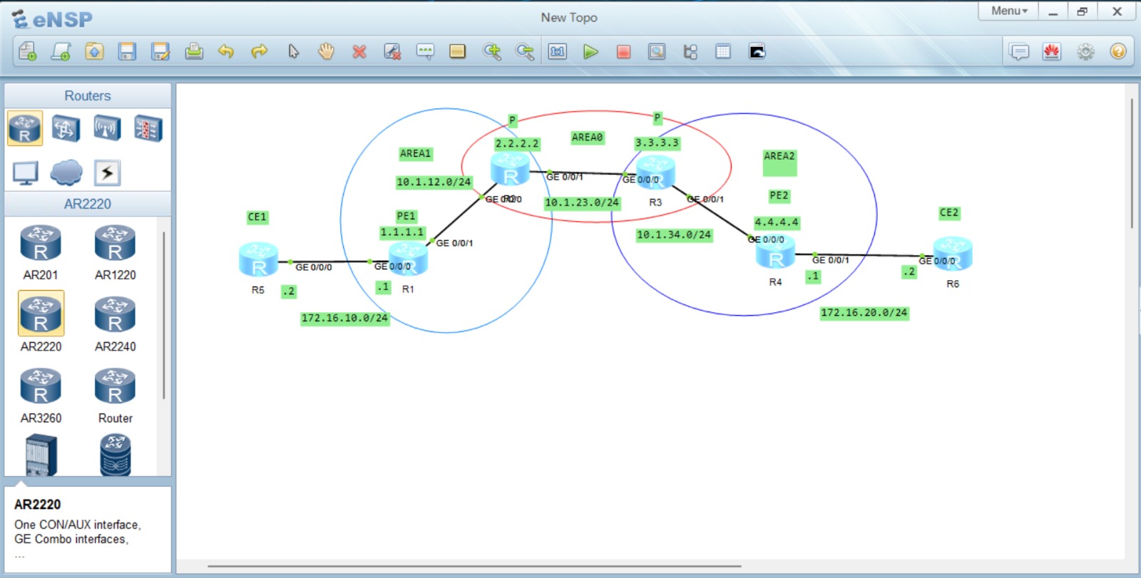
There are six routers:
| Router | Role | Loopback |
|---|---|---|
| R5 | CE1 (customer) | 10.100.1.1/32 (LoopBack1) |
| R1 | PE1 | 1.1.1.1/32 |
| R2 | P | 2.2.2.2/32 |
| R3 | P | 3.3.3.3/32 |
| R4 | PE2 | 4.4.4.4/32 |
| R6 | CE2 (customer) | 10.200.2.1/32 (LoopBack1) |
Links:
| Link | Block | Ends | Role |
|---|---|---|---|
| R1–R2 | 10.1.12.0/24 | R1 .1, R2 .2 | backbone, OSPF Area 1 |
| R2–R3 | 10.1.23.0/24 | R2 .2, R3 .3 | backbone, OSPF Area 0 |
| R3–R4 | 10.1.34.0/24 | R3 .3, R4 .4 | backbone, OSPF Area 2 |
| R5–R1 | 172.16.10.0/24 | R5 .2, R1 .1 | PE–CE, inside the VPN instance |
| R6–R4 | 172.16.20.0/24 | R6 .2, R4 .1 | PE–CE, inside the VPN instance |
The AS number is 65000, both PEs are in the same AS. So the session between the PEs is iBGP.
On the CE side I used a loopback each (/32) instead of a real LAN. It’s enough for testing and doesn’t strain eNSP.
3. Step-by-step setup
Step 1: OSPF in the backbone
First, the PEs’ loopbacks (1.1.1.1 and 4.4.4.4) must be able to reach each other, because both LDP and BGP will be set up over these addresses. I used three different areas in the backbone (R2–R3 Area 0, R1–R2 Area 1, R3–R4 Area 2), so R2 and R3 became ABRs. A single area would have been enough, but I also wanted to see that multi-area doesn’t break the VPRN. I explained the area logic in the OSPF multi-area post.
R2 as an example (an ABR with legs in two areas):
ospf 1 router-id 2.2.2.2
 area 0
  network 2.2.2.2 0.0.0.0
  network 10.1.23.0 0.0.0.255
  quit
 area 1
  network 10.1.12.0 0.0.0.255
  quit
 quit
Every router’s loopback was written into the area it’s in, and the ABRs do the transfer between areas. Check on R1:
<R1>display ip routing-table protocol ospf
        2.2.2.2/32  OSPF    10   1           D   10.1.12.2       GigabitEthernet0/0/1
        3.3.3.3/32  OSPF    10   2           D   10.1.12.2       GigabitEthernet0/0/1
        4.4.4.4/32  OSPF    10   3           D   10.1.12.2       GigabitEthernet0/0/1
      10.1.23.0/24  OSPF    10   2           D   10.1.12.2       GigabitEthernet0/0/1
      10.1.34.0/24  OSPF    10   3           D   10.1.12.2       GigabitEthernet0/0/1
3.3.3.3 and 4.4.4.4 are inter-area because they come from other areas, but R1 doesn’t care. LDP and BGP only want the loopback to be reachable. ping -a 1.1.1.1 4.4.4.4 works.
Step 2: MPLS and LDP
Done on the PEs and the Ps (R1–R4), not on the CEs (R5, R6). R1:
system-view
mpls lsr-id 1.1.1.1
mpls
 quit
mpls ldp
 quit
interface GigabitEthernet0/0/1
 mpls
 mpls ldp
 quit
return
What the lines mean:
mpls lsr-id 1.1.1.1: The router’s MPLS identity. I give it the loopback, because a loopback doesn’t go down.mpls: Turns on MPLS router-wide.mpls ldp: Turns on LDP globally.mpls+mpls ldpon the interface: Let labeled packets pass on that cable and look for a neighbor.
Labels are only turned on on the backbone interfaces. They’re not written on the customer-facing interface, because the customer sends plain IP packets and the PE adds the label.
Check (from R2):
<R2>display mpls ldp session

 PeerID             Status      LAM  SsnRole  SsnAge      KASent/Rcv
 ------------------------------------------------------------------------------
 1.1.1.1:0          Operational DU   Active   0000:00:04  18/18
 3.3.3.3:0          Operational DU   Passive  0000:00:02  9/9
What matters is that it’s Operational. Active/Passive is not a health indicator: the one with the bigger LSR ID starts the TCP connection (Active), the smaller one accepts it (Passive). R2 (2.2.2.2) is Active toward R1 (1.1.1.1) because it’s bigger, and Passive toward R3 (3.3.3.3) because it’s smaller.
LAM: DU means Downstream Unsolicited: neighbors advertise the label on their own without being asked.
I tested from R1 that the LSP was set up end to end:
<R1>tracert lsp ip 4.4.4.4 32
  LSP Trace Route FEC: IPV4 PREFIX 4.4.4.4/32 , press CTRL_C to break.
  TTL   Replier            Time    Type      Downstream
  0                                Ingress   10.1.12.2/[1026 ]
  1     10.1.12.2          20 ms   Transit   10.1.23.3/[1026 ]
  2     10.1.23.3          30 ms   Transit   10.1.34.4/[3 ]
  3     4.4.4.4            20 ms   Egress
A normal tracert tests the IP layer. tracert lsp tests the MPLS layer: it says “follow the label path set up for 4.4.4.4/32”. Seeing the labels is proof that the LSP really exists. A label has local meaning: R1 gives the packet to R2 with 1026, R2 also gives it to R3 with 1026 (a coincidence, the numbers vary by router), and R3 turns the label into 3. 3 is a special value, implicit-null: R4 is saying “drop the label before the last hop” (PHP, penultimate hop popping), and R3 removes the label and gives the packet to R4 as plain IP.
Step 3: VPN instance and PE–CE links
This is the VPRN itself. R1 (PE1):
system-view
ip vpn-instance VPRN_SERVICE
 ipv4-family
  route-distinguisher 65000:100
  vpn-target 65000:100 both
  quit
 quit
interface GigabitEthernet0/0/0
 ip binding vpn-instance VPRN_SERVICE
 ip address 172.16.10.1 24
 quit
ip route-static vpn-instance VPRN_SERVICE 10.100.1.1 32 172.16.10.2
return
ip vpn-instance VPRN_SERVICE: Creates a separate, customer-specific routing table (VRF).route-distinguisher 65000:100: Makes this VRF’s routes unique in BGP.vpn-target 65000:100 both:bothmeans both export and import. Since both PEs have the same RT, they take each other’s routes.ip binding vpn-instance: Binds the customer-facing interface to that VRF. Binding deletes the IP, so it’s written before the IP.ip route-static vpn-instance ...: Tells the PE’s VRF “CE1’s loopback is reached through this next hop”.
R4 (PE2) has the same logic, the interface facing its own CE and the route are different: 172.16.20.1/24 and 10.200.2.1/32 → 172.16.20.2.
There is no VPN instance on the CEs. R5 and R6 are ordinary routers: an IP on the interface, a loopback, and a default route to the PE:
interface GigabitEthernet0/0/0
 ip address 172.16.10.2 24
 quit
interface LoopBack1
 ip address 10.100.1.1 32
 quit
ip route-static 0.0.0.0 0 172.16.10.1
The customer isn’t even aware the VPN exists, the only thing it knows is “outside = PE”.
Step 4: MP-BGP between the PEs
I don’t write any BGP on the P routers (R2, R3). Only the two PEs:
R1:
bgp 65000
 router-id 1.1.1.1
 peer 4.4.4.4 as-number 65000
 peer 4.4.4.4 connect-interface LoopBack0
 ipv4-family unicast
  undo peer 4.4.4.4 enable
  quit
 ipv4-family vpnv4
  peer 4.4.4.4 enable
  quit
 ipv4-family vpn-instance VPRN_SERVICE
  import-route static
  quit
 quit
R4 is the same, with neighbor 1.1.1.1.
peer 4.4.4.4 as-number 65000: Same AS, so iBGP.connect-interface LoopBack0: The session is set up from the loopback, so even if a physical link goes down, the session lives on if OSPF finds another path.undo peer ... enable(unicast): I turn off normal IPv4 route exchange, this neighborship is only for the VPN.ipv4-family vpnv4+peer ... enable: The address family that carries VPN routes (RD + RT + label).ipv4-family vpn-instance+import-route static: Takes the static route in the VRF into BGP, so the remote PE learns it.
Step 5: Verification
BGP session (R4):
<R4>display bgp vpnv4 all peer

 BGP local router ID : 4.4.4.4
 Local AS number : 65000
 Total number of peers : 1		  Peers in established state : 1

  Peer            V          AS  MsgRcvd  MsgSent  OutQ  Up/Down       State PrefRcv
  1.1.1.1         4       65000        3        3     0 00:00:38 Established       2
VPN routes:
<R4>display ip routing-table vpn-instance VPRN_SERVICE
Destination/Mask    Proto   Pre  Cost      Flags NextHop         Interface

     10.100.1.1/32  IBGP    255  0          RD   1.1.1.1         GigabitEthernet0/0/0
     10.200.2.1/32  Static  60   0          RD   172.16.20.2     GigabitEthernet0/0/1
    172.16.20.0/24  Direct  0    0           D   172.16.20.1     GigabitEthernet0/0/1
10.100.1.1/32 arrived in R4’s VRF table as IBGP, and the next hop is R1’s loopback (1.1.1.1). The RD flag shows that the route reaches its next hop recursively, that is, through the LDP LSP to 1.1.1.1. The outgoing interface is the backbone port facing R3 (GigabitEthernet0/0/0). The customer traffic leaves with a label.
The real test: from CE1 to CE2’s loopback, giving my own loopback as the source:
<R5>ping -a 10.100.1.1 10.200.2.1
  PING 10.200.2.1: 56  data bytes, press CTRL_C to break
    Reply from 10.200.2.1: bytes=56 Sequence=1 ttl=251 time=40 ms
    Reply from 10.200.2.1: bytes=56 Sequence=2 ttl=251 time=50 ms
    Reply from 10.200.2.1: bytes=56 Sequence=3 ttl=251 time=60 ms
    Reply from 10.200.2.1: bytes=56 Sequence=4 ttl=251 time=50 ms
    Reply from 10.200.2.1: bytes=56 Sequence=5 ttl=251 time=50 ms

  5 packet(s) transmitted
  5 packet(s) received
  0.00% packet loss
-a matters: the source address should be the loopback, so that R6’s return route (10.100.1.1) goes through the VPN.
<R5>tracert -a 10.100.1.1 10.200.2.1
 1 172.16.10.1 20 ms  1 ms  20 ms
 2 10.1.12.2 30 ms  40 ms  40 ms
 3 10.1.23.3 40 ms  40 ms  30 ms
 4 172.16.20.1 40 ms  30 ms  40 ms
 5 172.16.20.2 40 ms  40 ms  50 ms
Path: R5 → R1 (PE1) → R2 (P) → R3 (P) → R4 (PE2) → R6. There’s something interesting here: in a tracert from the customer side, the addresses of the P routers in the backbone are visible (10.1.12.2, 10.1.23.3). In MPLS, the TTL is copied into the label by default, so the P routers send an ICMP reply when the TTL runs out. Operators usually don’t want to show the backbone to the customer, they turn this off with undo ttl-propagate and the tracert shows up as a single hop. I didn’t turn it off in this lab, seeing the path was useful to me.
Finally I verify the main claim of VPRN: the P router doesn’t see customer routes. R2’s global routing table:
<R2>display ip routing-table
Routing Tables: Public
         Destinations : 15       Routes : 15

Destination/Mask    Proto   Pre  Cost      Flags NextHop         Interface

        1.1.1.1/32  OSPF    10   1           D   10.1.12.1       GigabitEthernet0/0/0
        2.2.2.2/32  Direct  0    0           D   127.0.0.1       LoopBack0
        3.3.3.3/32  OSPF    10   1           D   10.1.23.3       GigabitEthernet0/0/1
        4.4.4.4/32  OSPF    10   2           D   10.1.23.3       GigabitEthernet0/0/1
      10.1.12.0/24  Direct  0    0           D   10.1.12.2       GigabitEthernet0/0/0
      10.1.23.0/24  Direct  0    0           D   10.1.23.2       GigabitEthernet0/0/1
      10.1.34.0/24  OSPF    10   2           D   10.1.23.3       GigabitEthernet0/0/1
      (127.x and the other Direct lines trimmed)
Only the backbone is in the table: the loopbacks and the P’s own links. 10.100.1.1 and 10.200.2.1 aren’t there, 172.16.x.x isn’t there. On top of that, R2 doesn’t even run BGP. So the packet from CE1 to CE2 passed through R2 (we saw it in the tracert), but R2 forwarded it not by looking at the IP, only by looking at the LDP label on top. Customer routes live in the PEs’ VRF tables and inside MP-BGP. This is VPRN’s guarantee of isolating the P router from the customer.
4. Where I got stuck
1. There was no IP on the interface, the ping didn’t go through. ping -vpn-instance VPRN_SERVICE 172.16.10.2 failed with 100% loss. I thought I had looked at the IP, but these two lines in the display interface GigabitEthernet0/0/0 output told the whole story:
Line protocol current state : DOWN
Internet protocol processing : disabled
Internet protocol processing : disabled means there’s no IP address on the interface. Physically it’s UP, but since there’s no IP the protocol is DOWN. The cause: the ip binding vpn-instance command deletes the IP on the interface. The order should be bind first, then write the IP.
2. undo ospf 1 didn’t work. While rebuilding the backbone, I pasted a block starting with undo ospf 1 into every router. Huawei asks for confirmation on this command, “Continue? [Y/N]”, and the next line I pasted (interface ...) became the answer to that question, so the deletion was cancelled. Result: the old network lines stayed below the new ones and the loopbacks sat in the wrong area. I noticed when I looked at the contents of ospf 1 with display current-configuration configuration ospf. Fix: type the undo ospf 1 command on its own and answer y, then paste the block.
3. The ping to the loopback didn’t go through. I had given the router-id by hand, but the loopback interface wasn’t defined. The router-id is only a name OSPF gives itself, not an address you can ping. The loopback needs an IP and a network x.x.x.x 0.0.0.0 line.
4. Writing a VPN instance on the CEs too. For a moment I thought the CEs also needed ip binding. They don’t: the VRF is the PE’s tool for keeping a separate table for more than one customer. The customer’s own router is an ordinary router, it has a single customer, so it doesn’t need a separate table.
5. Summary
- In the backbone, OSPF makes the loopbacks reachable, and LDP generates a label for each loopback.
- On the PEs, the VPN instance gives the customer a separate table, the RD makes the route unique, and the RT directs the route to the right VRF.
- Between the PEs, MP-BGP (VPNv4) carries the customer routes, the P routers have nothing to do with it.
- The customer packet gets two labels at PE1: the outer label (LDP, the path to the remote PE), the inner label (BGP, which VRF).
- Nokia and Huawei do the same job. The difference is mostly in syntax: on Nokia the service is in a single
vprnblock, on Huawei the VRF and the interface binding are separate commands. The transport tunnel is chosen explicitly on Nokia (auto-bind-tunnel), on Huawei the LDP LSP is the default.