1. Goal
In the PE–CE eBGP post I connected customer sites to the PE with eBGP. This time I’ll try OSPF on the same topology. There are two reasons:
- If OSPF is already running in the customer’s network, instead of converting it to BGP, you may want to carry OSPF end to end over the operator’s network.
- When I set up both methods in the same lab, I can see the differences with my own eyes. Which one is preferred and why, I also sum up at the end of the post.
I wrote about the same topic on Nokia with eBGP: PE–CE eBGP (Nokia). In this post I only touch on Nokia briefly.
I set up the commands on my simulator (ugbak.com/simulasyon) and took the outputs from there. On eNSP or a real device there may be small differences depending on the version; I noted where differences are expected inside the post.
2. The big picture: the PE is a “translator”
In eBGP, the route passed from the customer to the operator in the same language (BGP). With OSPF it’s different: the customer speaks OSPF, while the transport between PEs in the MPLS core is done with MP-BGP (vpnv4). So the PE has to translate in both directions:
- CE → PE (OSPF): The CE tells the PE about its LAN with OSPF. The PE translates it from the OSPF language to the BGP language (
import-route ospf 2) and sends it to the remote PE with vpnv4. - PE → PE (vpnv4): The route is tagged with the RD and RT and passes through the core. The P routers don’t see the customer route.
- PE → CE (OSPF): The remote PE translates this route from the BGP language to the OSPF language (
import-route bgp) and gives it to its own CE.
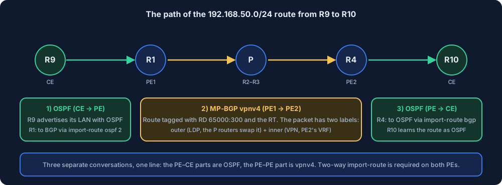
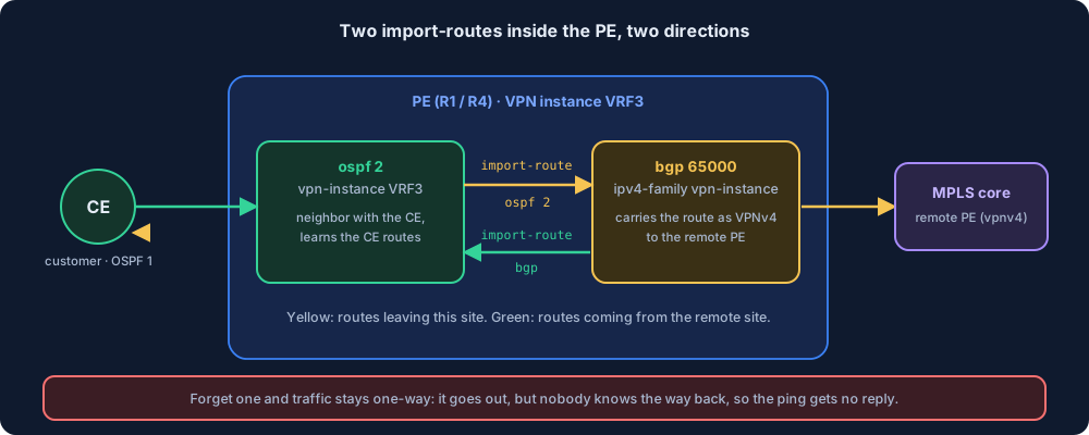
This translation is done with two separate commands, and both are needed. I explain from my own lab in section 7 what happens when you forget one of them.
3. Topology and IP plan
The topology is the same as in the eBGP post: R1 = PE1, R2 and R3 = P, R4 = PE2. Customer C’s two CEs are R9 and R10. Only the PE–CE protocol changes.
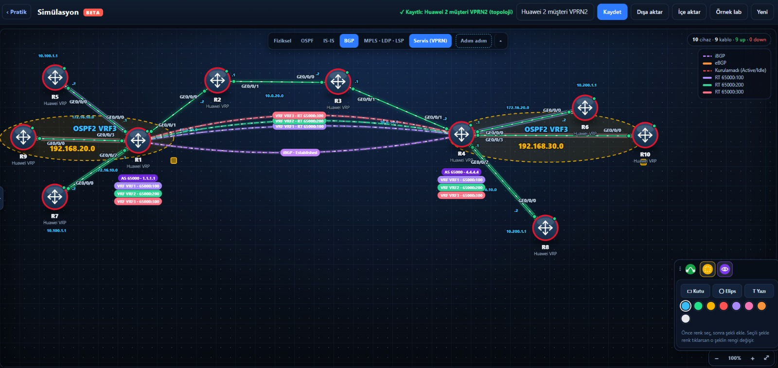
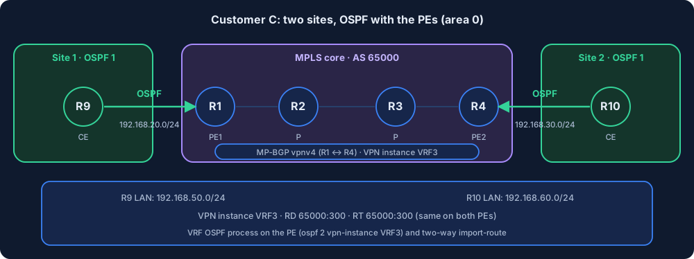
| Router | Role | OSPF | PE–CE link | LAN (LoopBack1) |
|---|---|---|---|---|
| R9 | CE (site 1) | process 1, area 0 | 192.168.20.0/24 (R9 .2, R1 .1) | 192.168.50.1/24 |
| R1 | PE1 | process 2, VRF3 | GE0/0/3 | |
| R4 | PE2 | process 2, VRF3 | GE0/0/3 | |
| R10 | CE (site 2) | process 1, area 0 | 192.168.30.0/24 (R10 .2, R4 .1) | 192.168.60.1/24 |
VPN instance VRF3: RD 65000:300, RT 65000:300 (the same on both PEs). On the PEs, the customer’s OSPF process is a separate process: independent of the global OSPF process (process 1, in the core).
Why a separate OSPF process on the PE?
The OSPF in the PE’s general (global) table is for the core network: the PEs, the Ps and the loopbacks talk there. The customer’s routes shouldn’t mix into that table. That’s why on Huawei a separate OSPF process is opened for each VRF:
ospf 2 vpn-instance VRF3
The process number (2) is a local label, but you need to use the same number when writing import-route ospf 2. Since a router can have more than one OSPF process, the number decides which one routes are taken from. There’s no such number in BGP, because a router runs a single BGP process; that’s why when taking routes into OSPF you only write import-route bgp.
4. Setup
Step 1: VPN instance and interface on the PE
On R1:
system-view
ip vpn-instance VRF3
 ipv4-family
  route-distinguisher 65000:300
  vpn-target 65000:300 both
 quit
quit
interface GigabitEthernet0/0/3
 undo shutdown
 ip binding vpn-instance VRF3
 ip address 192.168.20.1 24
 quit
The same on R4: 192.168.30.1 24 on the interface. ip binding comes before the IP, otherwise the IP on the interface is deleted.
Step 2: VRF-specific OSPF process and two-way import-route on the PE
On R1:
ospf 2 vpn-instance VRF3
 import-route bgp
 area 0
  network 192.168.20.0 0.0.0.255
 quit
quit
bgp 65000
 ipv4-family vpn-instance VRF3
  import-route ospf 2
 quit
quit
The same on R4, with network 192.168.30.0 0.0.0.255.
Line by line:
ospf 2 vpn-instance VRF3: The OSPF process bound to VRF3. When you go inside, the prompt becomes[R1-ospf-2].import-route bgp: Take into this OSPF process the BGP routes coming from the remote site over the VPN, that is, give them to the CE as OSPF routes.area 0+network ... 0.0.0.255: Turn on OSPF on the PE–CE link.0.0.0.255is a wildcard mask: the inverse of the subnet mask (the inverse of/24). So the interfaces in the 192.168.20.0 network join OSPF.import-route ospf 2(inside BGP, underipv4-family vpn-instance VRF3): Take the routes you learned with OSPF from the CE into BGP and send them to the remote PE with vpnv4. The 2 here is the OSPF process number above.
Step 3: OSPF on the CE
On R9:
system-view
sysname R9
interface GigabitEthernet0/0/0
 undo shutdown
 ip address 192.168.20.2 24
 quit
interface LoopBack1
 ip address 192.168.50.1 24
 quit
ospf 1
 area 0
  network 192.168.20.0 0.0.0.255
  network 192.168.50.0 0.0.0.255
The same on R10: 192.168.30.2 24, LoopBack1 192.168.60.1 24, network 192.168.30.0 0.0.0.255 and network 192.168.60.0 0.0.0.255.
The CE side is an ordinary OSPF setup. The CE knows nothing about the VRF; it thinks the PE is an ordinary OSPF neighbor.
Step 4 (I didn’t do this in this lab): domain-id
I didn’t write domain-id in my lab and everything worked. But you’ll often see this command in real networks, so I’m writing what it’s for.
import-route carries the route, while domain-id puts a tag on the route: “which OSPF domain did this route come from”. When the remote PE takes the route from BGP and gives it to the CE as OSPF, it looks at this tag:
- If the two PEs’
domain-ids are the same, the route goes to the CE as inter-area (Type 3,O IA). It behaves like “the same customer’s own OSPF”. - If they’re different (or one isn’t written at all and the other has a value), the route goes as external (Type 5,
O E2). It behaves like “it came from outside”.
Think of it like a mailbox: import-route carries the letter from one post office to the other, domain-id is the “from the same city?” stamp on the envelope. The stamp doesn’t decide whether the letter goes, it decides how it looks on the other side.
In practice you use the same domain-id at all the sites of a customer, so that the route looks the same type at every site and OSPF’s route preference rules stay predictable. Syntax:
ospf 2 vpn-instance VRF3
 domain-id 10
It must be the same value on both PEs (in my lab it’s on neither, so both are at the same default). The command is written inside the ospf <process> vpn-instance view. You’ll see its effect in section 6 of the post and in the route table.
I’ll verify this part separately on eNSP: with
domain-idleft the same and given different values, I’ll look withdisplay ospf routingat whether the route shows up asO IAorO E2on R10. I’ll add the result here.
5. Verification
Neighborship
On R1:
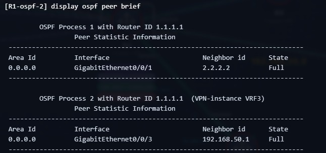
<R1> display ospf peer brief

	 OSPF Process 1 with Router ID 1.1.1.1
		  Peer Statistic Information
 ----------------------------------------------------------------------------
 Area Id          Interface                        Neighbor id      State
 0.0.0.0          GigabitEthernet0/0/1             2.2.2.2          Full
 ----------------------------------------------------------------------------

	 OSPF Process 2 with Router ID 1.1.1.1
		  Peer Statistic Information
 ----------------------------------------------------------------------------
 Area Id          Interface                        Neighbor id      State
 0.0.0.0          GigabitEthernet0/0/3             192.168.50.1     Full
 ----------------------------------------------------------------------------
There are two separate processes: Process 1 in the core with R2, Process 2 in VRF3 with the CE. The neighbor ID (192.168.50.1) is R9’s router ID; since I didn’t give it by hand on the CE, the biggest loopback address was chosen.
Route table
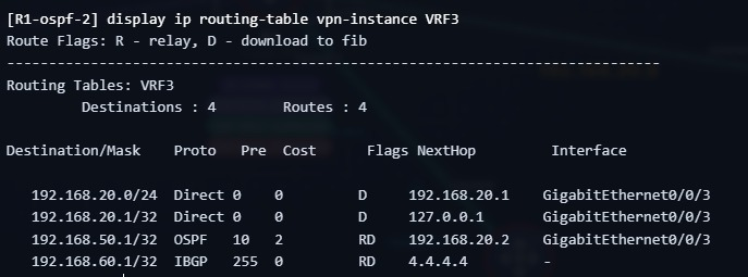
VRF3’s table on R1:
<R1> display ip routing-table vpn-instance VRF3

Destination/Mask    Proto   Pre  Cost      Flags NextHop         Interface

   192.168.20.0/24  Direct  0    0         D     192.168.20.1    GigabitEthernet0/0/3
   192.168.20.1/32  Direct  0    0         D     127.0.0.1       GigabitEthernet0/0/3
   192.168.50.1/32  OSPF    10   2         RD    192.168.20.2    GigabitEthernet0/0/3
   192.168.60.1/32  IBGP    255  0         RD    4.4.4.4         -
192.168.50.1/32OSPF: R9’s LAN came from the CE with OSPF.192.168.60.1/32IBGP, next hop 4.4.4.4: R10’s LAN came from R4 with vpnv4.
An important detail: I gave the LAN as /24, but OSPF advertised it as /32. On Huawei, a loopback interface always enters OSPF as a host route (/32), whatever its mask is. I expect the same behavior on a real device. If I had given the LAN to a real physical interface, I would see /24.
On R10:
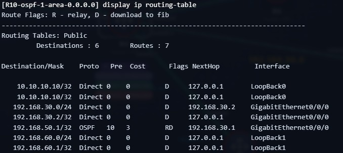
<R10> display ip routing-table

   192.168.30.0/24  Direct  0    0         D     192.168.30.2    GigabitEthernet0/0/0
   192.168.30.2/32  Direct  0    0         D     127.0.0.1       GigabitEthernet0/0/0
   192.168.50.1/32  OSPF    10   3         RD    192.168.30.1    GigabitEthernet0/0/0
   192.168.60.0/24  Direct  0    0         D     127.0.0.1       LoopBack1
   192.168.60.1/32  Direct  0    0         D     127.0.0.1       LoopBack1
R10 learned R9’s LAN as OSPF, next hop the PE (192.168.30.1). This is the only thing R10 knows: “the remote LAN is reached through the PE”. It doesn’t know there’s MPLS in between. My expectation: on a real device this route shows up on R10 as inter-area (OSPF Type 3), and you can see this in the display ospf routing output. I explain why in section 6.
End-to-end ping
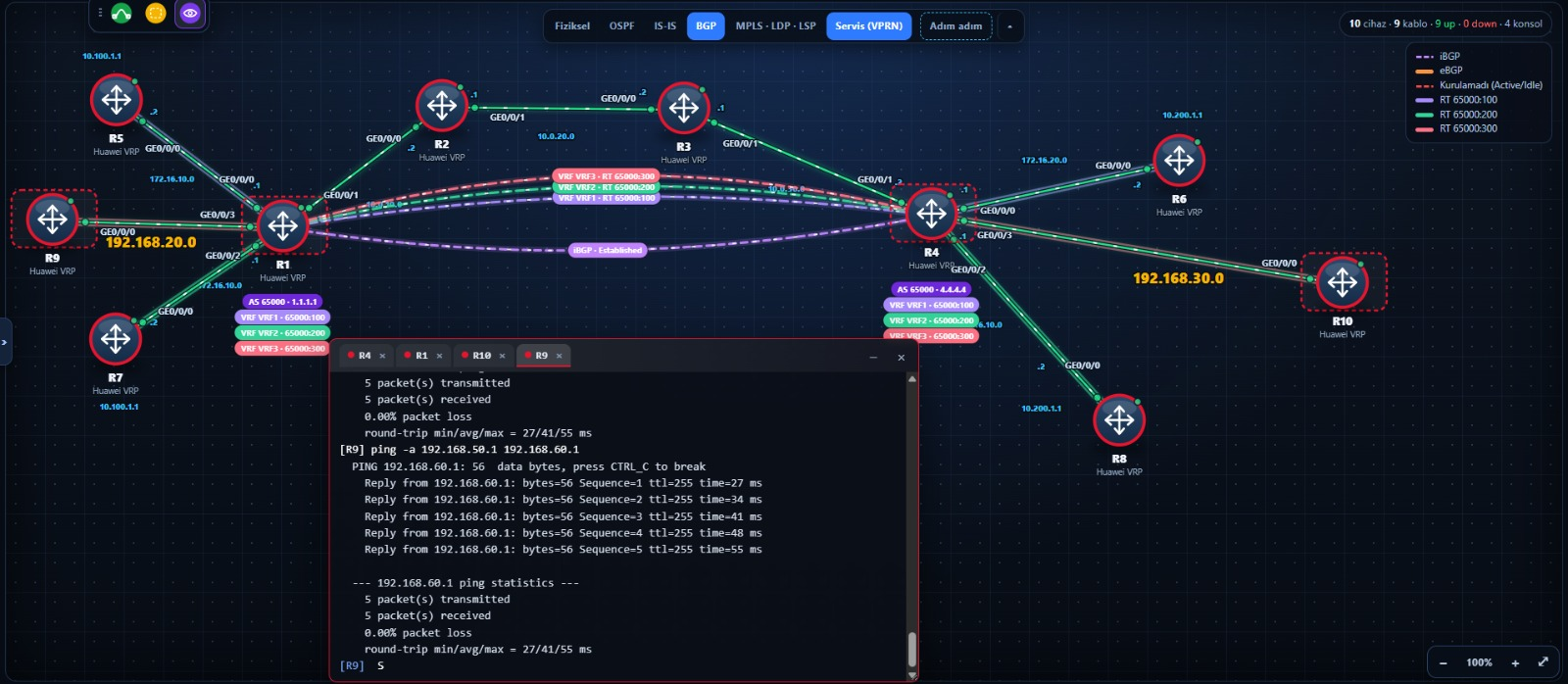
<R9> ping -a 192.168.50.1 192.168.60.1
  PING 192.168.60.1: 56  data bytes, press CTRL_C to break
    Reply from 192.168.60.1: bytes=56 Sequence=1 ttl=255 time=27 ms
    ...
  --- 192.168.60.1 ping statistics ---
    5 packet(s) transmitted
    5 packet(s) received
    0.00% packet loss
-a 192.168.50.1 makes the source address the LAN address. If I don’t give a source, the packet goes out from the link address (192.168.20.2) and since the other side doesn’t know that network, the reply doesn’t come back (see 7.4).
6. Where OSPF behaves differently inside a VPN
A few things you’re used to from normal OSPF change here. All of them are defined in RFC 4577:
- The route type changes. The remote site’s LAN usually arrives at the remote CE as inter-area (Type 3), even if over there it’s a route in the same area (intra-area). Because the route passes through BGP and re-enters OSPF. This happens if the two PEs’ domain-ids are the same (by default both are the same). If the domain-ids are different, the route is given as external (Type 5). This is used to separate two different OSPF domains from each other.
- DN bit (Down bit). The PE marks this bit in the Type 3 and Type 5 LSAs it gives to the CE. If another PE sees an LSA carrying this bit, it ignores it. The goal is to prevent a loop: the route shouldn’t leak back to another PE through the CE and re-enter BGP. In eBGP, AS_PATH did this job.
- The metric is carried. The OSPF cost is carried in BGP as the MED (the RFC default: OSPF distance + 1), and the remote PE converts it into an OSPF metric. That’s why you see a number like cost 3 on R10.
- The backup (backdoor) link problem. If there’s also a direct link between the two sites, the route learned over that link (intra-area) is preferred over the inter-area route coming over MPLS. To keep the traffic on the VPN, a sham-link is set up between the PEs. It’s outside the scope of this post, but it’s one of the examples that shows why using OSPF gets harder in real life.
These don’t exist in eBGP: there it’s substitute-as and AS_PATH, in OSPF it’s the DN bit and domain-id. I put the comparison into a table in section 8.
7. Where I got stuck
I’m writing in order what I went through while setting up the lab step by step. All of them are real error messages and real situations.
7.1 R9 can’t see the remote LAN: one of the two import-routes is missing
The PE side looked right. In R1’s VRF3 table the remote LAN (192.168.60.1/32) was there as IBGP, so the VPN was working. But on the CE side:
<R9> display ip routing-table 192.168.60.1
Info: The route does not exist.
The cause: import-route ospf 2 (inside BGP) sends this site’s routes out. To give the routes coming from the remote site to the CE, a separate command is needed in the OSPF process: import-route bgp. I had mixed the two up. This is how I tell them apart:
| Where | Command | Direction |
|---|---|---|
bgp 65000 → ipv4-family vpn-instance VRF3 | import-route ospf 2 | From the CE to the core: this site’s routes into the VPN |
ospf 2 vpn-instance VRF3 | import-route bgp | From the core to the CE: the remote site’s routes to the CE |
Diagnosis tip: if the route is on the PE but not on the CE, import-route bgp is missing. If the route isn’t on the PE either, look at an earlier link of the chain (7.5).
7.2 Forgetting to look at the VRF table on the PE
When I typed plain display ip routing-table on R1, I couldn’t see the customer’s routes: that command shows the general table. The customer routes are in the VRF’s own table:
<R1> display ip routing-table vpn-instance VRF3
In the same way, display ospf peer lists both processes together; the customer’s neighbor shows up under Process 2 (the output in section 5).
7.3 The reply doesn’t come back when I ping the remote CE from the PE
I pinged the remote CE’s LAN from R4:
<R4> ping -vpn-instance VRF3 192.168.50.1
    Request time out
The packet goes out but nothing comes back. When pinging an address inside a VPN from the PE, -vpn-instance VRF3 is needed (a ping without the VRF looks at the general table). But even with the VRF no reply came, because the packet’s source is R4’s PE–CE link address (192.168.30.1). R9 has no return route to this network: that link is a Direct route, and import-route ospf 2 only takes OSPF routes into BGP. This isn’t a bug; pinging the remote CE from the PE just doesn’t work like this. The right test is CE to CE, with the LAN addresses:
<R9> ping -a 192.168.50.1 192.168.60.1
If you also want to show the PE’s link networks, you can add import-route direct. But in real service networks, exposing link addresses to the customer is usually not wanted.
7.4 ping -a “Bind source address failed”
When I typed ping -a 192.168.50.1 192.168.60.1 on R4:
Error: Bind source address failed.
The source address given with -a has to be on that router’s own interface. 192.168.50.1 is R9’s address, it’s not on R4. The same command works on R9.
7.5 Where in the chain is the route getting lost?
The remote LAN didn’t arrive in R4’s VRF3 table, and it didn’t reach R1 either. Since the chain has four links, I looked backward:
- Does the LAN enter OSPF on R10? (Is the neighborship Full in
display ospf peer brief, do the OSPFnetworklines cover the LAN?) - Does it show up as OSPF in R4’s VRF3 table?
- Is it in
display bgp vpnv4 vpn-instance VRF3 routing-tableon R4? (Isimport-route ospf 2in the right place?) - Did it arrive at R1 with vpnv4 and enter the VRF3 table? (Do the RTs match?)
In my lab the cause was the first item: there was no network line for the LAN on R10. The neighborship was Full, the link network was in OSPF, but 192.168.60.0 had never entered OSPF. Since R10 didn’t advertise that network itself, R4 couldn’t learn it either, and the rest of the chain stayed empty. Thinking “OSPF is fine” because the neighborship is Full is a trap: the neighborship and the advertisement of the route are separate things. What advertises the route is the network line (or ospf enable on the interface).
On top of that, R10’s OSPF section was messy: I had entered two different wildcards (0.0.0.3 and 0.0.0.255) for the same network. Extra lines don’t break anything on their own, but they make it harder to read. The clean and correct version:
ospf 1
 area 0.0.0.0
  network 192.168.30.0 0.0.0.255
  network 192.168.60.0 0.0.0.255
Rule: when looking backward, start from the very end. If the CE didn’t put its own LAN into OSPF, whatever you do on the PE side is pointless.
7.6 I gave the LAN as /24 but I see /32
R9’s LoopBack1 is 192.168.50.1/24. But in R1’s table there’s 192.168.50.1/32. I thought this was a bug, it wasn’t: on Huawei, loopbacks enter OSPF as host routes (the note in section 5). In practice it has no effect, because ping and forwarding work with /32 too. But if you want to describe a “LAN”, use a real interface instead of a loopback.
8. Comparison with eBGP
The differences that come out when you set up the two posts on the same topology:
| Topic | PE–CE eBGP | PE–CE OSPF |
|---|---|---|
| Extra setting on the PE | peer ... as-number inside the VRF | VRF-specific OSPF process + import-route bgp + import-route ospf 2 in BGP |
| Extra setting on the CE | bgp 65001, peer, network | ospf 1, area 0, network |
| How the CE sees the route | EBGP, AS path 65000 ... | OSPF (inter-area), the metric is carried |
| Both sites in the same AS | Trap: substitute-as is needed | No such problem (no AS path) |
| Loop prevention | AS_PATH | DN bit, route tag, domain-id |
| Preference between multiple routes | local-pref, MED, community, route-policy | Cost, route type (intra/inter/external) |
| Limiting the number of prefixes | peer ... route-limit | Hard: the PE takes in the customer’s LSAs |
| Load on the PE | Only prefixes | Every change in the customer’s domain means SPF and LSAs |
| Backup link scenario | Normal BGP preference | A sham-link may be needed |
| Does the customer keep its own IGP end to end? | No (BGP sits in between) | Yes, the OSPF domain is also visible at the other end of the VPN |
Short summary: The OSPF setup is simple on the CE side and complex on the PE side. With eBGP it’s the other way around. Since the operator’s real load is on the PE, the table tips in favor of eBGP.
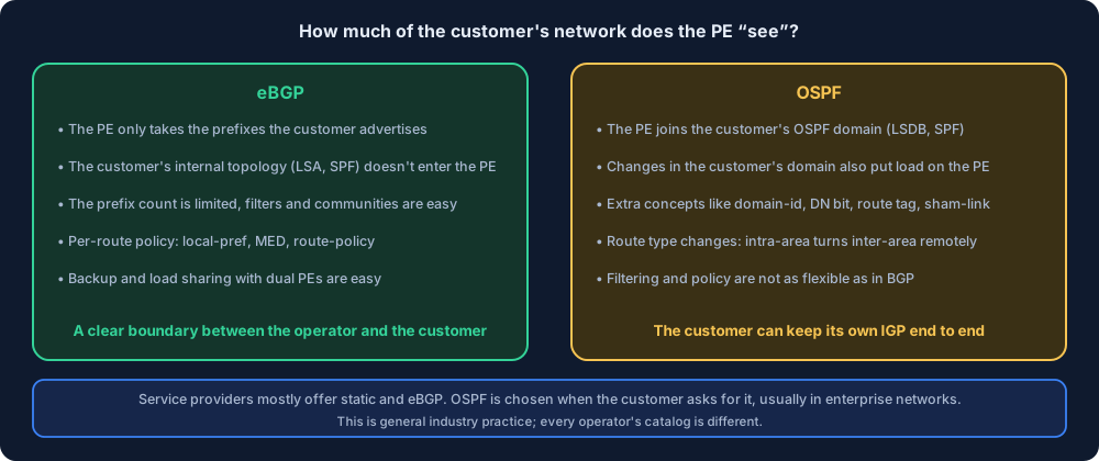
9. Which one in real life, and why?
While writing this I also asked myself: will I come across the setup in this lab in the field? My answer is this, but with a warning: what follows is general industry practice and technical reasoning; I don’t have hard statistics, and every operator’s service catalog is different.
Operators mostly offer static routes and eBGP. Some give OSPF to customers who ask for it, some don’t offer it at all. The reasons:
- The PE doesn’t want to get inside the customer. With OSPF, the PE joins the customer’s OSPF domain: it takes in LSAs, it runs SPF. If a link flaps in the customer’s network, the PE’s CPU gets tired too. For an operator carrying thousands of customers on the same PE, this is a serious risk. With eBGP, the PE only takes the prefixes the customer advertises and doesn’t see the customer’s internal structure.
- The boundary should be clear. BGP is the natural boundary protocol between two administrative domains: the number of prefixes is limited, policy is applied with filters and communities. In OSPF this control is much weaker.
- Policy and traffic management. Load sharing, backup and the preferred path for a dual-PE customer: easy in BGP with local-pref, MED and communities; in OSPF it’s done with metric games.
- OSPF has extra complexity inside a VPN. Domain-id, DN bit, route tag, sham-link, the route type changing. When the customer doesn’t know these, the support load grows.
- Scaling. A separate OSPF process is opened for every VRF; there’s a limit to the number of processes and neighbors on a device.
OSPF is still used, especially in these cases:
- The customer is an enterprise network and wants to keep its own OSPF across the WAN.
- The customer has no BGP knowledge or desire.
- A migration from an old leased-line network to MPLS VPN is ongoing, and they don’t want to change the existing routing structure.
- The operator offers it as part of a managed service.
So in short: from the operator’s point of view eBGP is cleaner, and OSPF is possible if the customer asks for it. That’s why it’s useful to know the setup in this post, but in the field you’re more likely to come across static and eBGP first.
10. Differences from Nokia
Nokia SR OS has the same logic: the customer’s OSPF runs inside the VPRN service, and one transfer is needed in each direction. The command side is different. I haven’t verified the Nokia part of this table in my own lab yet (there’s no Nokia VPRN OSPF in the simulator), so I’m only writing the general direction; I’ll write the Nokia post separately with outputs.
| Topic | Nokia SR OS | Huawei VRP |
|---|---|---|
| Where OSPF runs | The OSPF instance inside the VPRN service | A separate process, ospf 2 vpn-instance VRF3 |
| CE route → VPN | VRF export policy | import-route ospf 2 in BGP |
| VPN route → CE | OSPF export policy | import-route bgp in OSPF |
| Transfer logic | The policy is explicit and mandatory | A single-line command |
On Nokia, since what is transferred where is written explicitly in the policy, it teaches more; on Huawei it’s a single line. We saw the same difference in the eBGP post.
11. Summary
- In PE–CE OSPF, the customer speaks OSPF, the core speaks vpnv4. The PE is a two-way translator:
import-route ospf 2(inside BGP) andimport-route bgp(inside OSPF). Both are needed. - On the PE, a separate OSPF process for the customer:
ospf 2 vpn-instance VRF3. Plainospf 1is for the core. - Since there’s a single process in BGP,
import-route bgphas no number; since there can be several processes in OSPF,import-route ospf 2has a number. - On the PE, look at the customer’s table with
display ip routing-table vpn-instance VRF3. Ping from inside the VPN:ping -vpn-instance VRF3. - In a CE-to-CE ping, give the LAN address as the source (
ping -a), the PE link networks aren’t spread to the CE. - If the route is on the PE but not on the CE,
import-route bgpis missing. If it’s not on the PE either, move backward along the chain. - Loopbacks enter OSPF as /32.
- OSPF’s rules inside a VPN: the route type becomes inter-area, the DN bit prevents loops, the domain-id must be the same, and a sham-link is needed if there’s a backup link.
- In real life operators mostly offer static and eBGP; OSPF shows up if the customer asks for it and in enterprise networks. The PE getting inside the customer’s domain and the extra complexity are the main reasons.
You can find the topology from this post ready-made on the Simulation page (Turkish UI): Yeni → Huawei → “PE–CE OSPF: üçüncü müşteri (Huawei)”. “Konfigle aç” (open with config) brings customers A, B and C set up. With “Sadece topoloji” (topology only), the configuration of R9 and R10 is up to you.
Practice the same setup: PE–CE OSPF lab (Huawei) (Turkish). The core comes ready, you set up OSPF on the CE, the VRF OSPF process on the PE and the two-way import-route.
Sources
- RFC 4577: OSPF as the Provider/Customer Edge Protocol for BGP/IP VPNs: domain identifier, DN bit, route tag, sham-link and carrying the OSPF cost in the MED.