1. Goal
In the two customers post I connected the CEs to the PE with static routes: ip route-static vpn-instance ... for the customer VRF on the PE, a default route on the CE. It does the job in a small environment. But if the customer had 50 sites, you’d have to write routes by hand at every site, and clean them up by hand when a site goes down.
In this post I add a new customer and connect the CEs to the PE with eBGP: the CE tells the PE about its own LAN, and the PE carries it to the other site across the MPLS core. If a site goes down, the route disappears on its own.
I wrote the same topic for Nokia too: PE–CE eBGP (Nokia). There, the part that took the most time was the export policy. On Huawei things are a bit shorter, but you get stuck in other places. You’ll see both side by side.
I set up the commands on my simulator (ugbak.com/simulasyon) and took the outputs from there. On eNSP or a real device there may be small differences depending on the version.
2. The big picture
The route travels along a three-part path:
- CE → PE (eBGP): The CE tells the PE about its LAN. This session is set up inside the customer’s VPN instance.
- PE → PE (MP-BGP,
vpnv4): The PE tags this route with the RD and RT and carries it to the remote PE. The P routers in between never see the customer route, they only look at the MPLS label. - PE → CE (eBGP): The remote PE takes the route into its own VPN instance and gives it to its own CE.
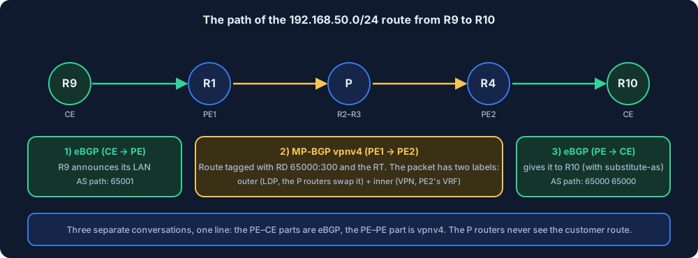
On the way, the packet also carries two labels: the outer label (LDP) takes the packet from PE1 to PE2, and the inner label tells PE2 which customer VRF to look at. I explained these two layers in the What is MPLS post.
3. Topology and IP plan
I’m using the lab from the previous post as is: R1 = PE1, R2 and R3 = P, R4 = PE2. Customers A and B (R5–R8) stay as they are. On top of that I add customer C: two new CEs, R9 and R10.
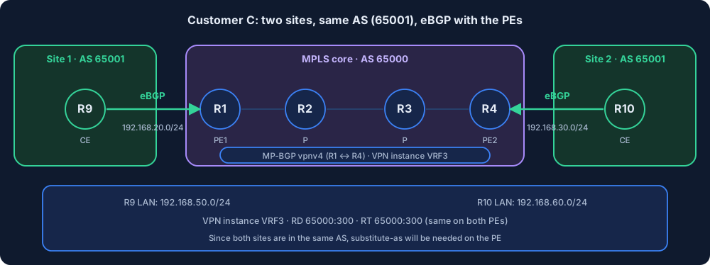
| Router | Role | AS | PE–CE link | LAN (LoopBack1) |
|---|---|---|---|---|
| R9 | CE (site 1) | 65001 | 192.168.20.0/24 (R1 .1, R9 .2) | 192.168.50.1/24 |
| R10 | CE (site 2) | 65001 | 192.168.30.0/24 (R4 .1, R10 .2) | 192.168.60.1/24 |
| Customer C | |
|---|---|
| VPN instance | VRF3 |
| RD / RT | 65000:300 / 65000:300 |
| Interface on the PE | GE0/0/3 |
| PE AS | 65000 |
Three points to watch:
- Both CEs are in the same AS (65001). This is on purpose: a customer’s two sites usually use the same AS. This has a consequence, we’ll see it in section 7.
- The PEs now have four interfaces (backbone, A, B, C). The AR1220 doesn’t have that many ports, add a module or use a bigger router. I wrote
GigabitEthernet0/0/3, change it according to your own interface name. - There are already VPRN_SERVICE and VPRN_B for A and B in the network. A new customer means only a new VPN instance on the PEs, you don’t touch the P routers.
Why is the LAN on the CE a loopback?
There’s no real LAN on the CE, I use LoopBack1 instead. There are two reasons: in the simulator and the lab there’s no need to set up an extra switch and PC, and a loopback never goes down, so it’s a nice target for the LAN to be always visible in BGP. In reality this 192.168.50.0/24 would be an office network, it would be the CE’s LAN interface, the logic is the same.
Why is the neighbor IP the link address, not the loopback?
I asked this question in the Nokia post, and the answer is the same here: eBGP neighbors must be directly connected by default (TTL = 1). Since the PE and the CE are on the two ends of the same link, the neighborship is set up with the link IP (peer 192.168.20.2). If you want to set up the neighborship from the loopback, you need ebgp-max-hop and a route to the loopback. Needless complexity for PE–CE.
4. The BGP block on Huawei: where is the neighbor written?
This is the most commonly confused place on Huawei. Inside the bgp 65000 block on the PE there are three separate places:
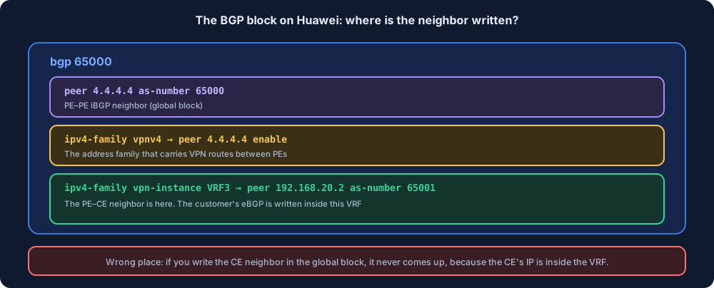
- Global block: the PE–PE neighbor (
peer 4.4.4.4 as-number 65000). ipv4-family vpnv4: the block that lets that neighbor carry VPN routes (peer 4.4.4.4 enable). These were already in the VPRN post.ipv4-family vpn-instance VRF3: the customer’s eBGP neighbor is written here.
The CE’s IP (192.168.20.2) is inside the VPN instance. The global table doesn’t know this address. If you write the neighbor in the global block, the session never comes up and there’s no error message either, the neighbor just stays in Idle or Active.
5. Setup
Step 1: VPN instance, interface and eBGP neighbor on the PE
On R1:
system-view
ip vpn-instance VRF3
 ipv4-family
  route-distinguisher 65000:300
  vpn-target 65000:300 both
 quit
quit
interface GigabitEthernet0/0/3
 undo shutdown
 ip binding vpn-instance VRF3
 ip address 192.168.20.1 24
 quit
bgp 65000
 ipv4-family vpn-instance VRF3
  peer 192.168.20.2 as-number 65001
The same on R4: give the interface 192.168.30.1 24, and let the neighbor be 192.168.30.2.
Watch three things:
ip bindingcomes before the IP. If the order is reversed, the IP on the interface is deleted. I warned about this for customers A and B too. On a real device it’s very common to spend hours wondering “why did my IP address disappear”.- The neighbor is written inside the
ipv4-family vpn-instance VRF3block (section 4). - There’s no static route and no
import-route static. The CE itself will give the route with BGP.
Step 2: BGP on the CE
On R9:
system-view
sysname R9
interface GigabitEthernet0/0/0
 undo shutdown
 ip address 192.168.20.2 24
 quit
interface LoopBack1
 ip address 192.168.50.1 24
 quit
bgp 65001
 peer 192.168.20.1 as-number 65000
 network 192.168.50.0 24
R10 the same way: interface 192.168.30.2 24, LoopBack1 192.168.60.1 24, neighbor 192.168.30.1, network 192.168.60.0 24.
There are two things on the CE side:
peer 192.168.20.1 as-number 65000is the neighbor’s AS. The PE’s AS (65000), not your own AS.network 192.168.50.0 24gives the LAN to BGP. This command only works if that prefix exists in the routing table (in our case, LoopBack1’s direct route). If the prefix isn’t in the table, it doesn’t go into BGP.
6. Verification
Neighborship
On R9:
<R9> display bgp peer

 BGP local router ID : 192.168.50.1
 Local AS number : 65001
 Total number of peers : 1                 Peers in established state : 1

  Peer            V          AS  MsgRcvd  MsgSent  OutQ  Up/Down       State PrefRcv

  192.168.20.1     4       65000        9        9     0 00:00:00  Established       1
When we see Established and PrefRcv 1, we understand the CE received one route from the PE.
To see the same neighborship on the PE from inside the VPN instance:
<R1> display bgp vpnv4 vpn-instance VRF3 peer
The neighbor shows up here. Plain display bgp peer on the PE only shows the global neighbors (4.4.4.4), it doesn’t show the CE neighbor.
Route table
<R1> display bgp vpnv4 vpn-instance VRF3 routing-table

 VPN-Instance VRF3, router ID 1.1.1.1:

 Total Number of Routes: 2
      Network            NextHop        MED        LocPrf    PrefVal Path/Ogn

 *>    192.168.50.0/24    192.168.20.2     0                    0       65001 i
 *>i   192.168.60.0/24   4.4.4.4         0          100       0       65001 i
The first line is from the local CE (eBGP, NextHop is the CE’s IP), the second line is from the remote PE (vpnv4, NextHop 4.4.4.4). Looking at the VPN instance’s IP table, both went into the routing table:
<R1> display ip routing-table vpn-instance VRF3

Destination/Mask    Proto   Pre  Cost      Flags NextHop         Interface

    192.168.20.0/24  Direct 0    0         D     192.168.20.1     GigabitEthernet0/0/3
    192.168.20.1/32  Direct 0    0         D     127.0.0.1       GigabitEthernet0/0/3
    192.168.50.0/24  EBGP   255  0         RD    192.168.20.2     GigabitEthernet0/0/3
   192.168.60.0/24  IBGP   255  0         RD    4.4.4.4         -
Pay attention to EBGP and IBGP: the PE–CE route is eBGP, the route between PEs is iBGP. So there’s both eBGP and iBGP in the same table.
End-to-end ping
<R9> ping -a 192.168.50.1 192.168.60.1
  PING 192.168.60.1: 56  data bytes, press CTRL_C to break
    Reply from 192.168.60.1: bytes=56 Sequence=1 ttl=255 time=27 ms
    ...
  --- 192.168.60.1 ping statistics ---
    5 packet(s) transmitted
    5 packet(s) received
    0.00% packet loss
With -a 192.168.50.1 I made the LAN address the source of the ping. If you don’t give a source, the packet goes out with the link address (192.168.20.2). Since the other side doesn’t know that address, the reply can’t come back and the ping fails. This is one of the most common causes of the “ping doesn’t work” complaint in PE–CE setups.
If you want, trace the path too:
<R9> tracert -a 192.168.50.1 192.168.60.1
 1 192.168.20.1 ...
 2 10.0.12.2 ...
 3 10.0.23.3 ...
 4 10.0.34.4 ...
 5 192.168.60.1 ...
The first hop is PE1 (192.168.20.1), the last hop is R10’s LAN. The ones in between are the interfaces of the core routers. The details of the output vary by version.
7. Where I got stuck
7.1 Both sites in the same AS: the route doesn’t reach R10
The setup in Steps 1 and 2 looks error-free: the neighborships are Established, R9’s LAN shows up on R4. But when I looked at R10’s table, only its own LAN was there. And the ping doesn’t go through:
<R10> display bgp routing-table

 Total Number of Routes: 1
      Network            NextHop        MED        LocPrf    PrefVal Path/Ogn

 *>    192.168.60.0/24   0.0.0.0         0                    0       i
The cause is eBGP loop prevention. The logic: BGP carries an AS path (AS_PATH) along with every route. Every AS the route passes through adds its own number to this list, just like stamping a passport. If a router sees its own AS number in the AS path of an incoming route, it thinks “this route has already been through me at some point, there’s a loop” and rejects it. This is the basic rule that keeps routes from looping forever at internet scale.
In our setup both sites are in the same AS (65001). Let’s follow the route’s path hop by hop:
- R9 → R1 (eBGP): R9 gives its own LAN and adds 65001 to the AS path:
[65001]. R1 (AS 65000) doesn’t see its own AS in the list and accepts it. - R1 → R4 (iBGP, vpnv4): The two PEs are in the same AS (65000) and iBGP doesn’t add an AS. The path stays as is:
[65001]. - R4 → R10 (eBGP): R4 adds its own AS on the way out to eBGP:
[65000 65001]. R10’s AS is 65001. It sees its own number in the list and rejects the route.
So the route gets as far as R4 and is turned away at R10’s door. The neighborship stays Established, there’s no error message, the route silently drops.
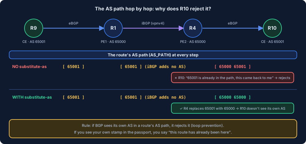
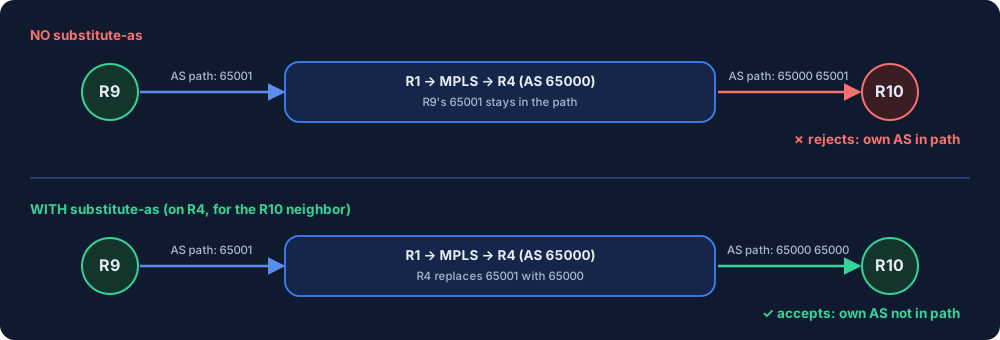
The fix is on the PE. When sending to the other site, the PE replaces the customer’s AS with its own AS. On both PEs, on the neighbor facing the CE:
bgp 65000
 ipv4-family vpn-instance VRF3
  peer 192.168.20.2 substitute-as     (on R1)
  peer 192.168.30.2 substitute-as     (on R4)
The substitute-as command does this: when the PE gives a route to the CE, it replaces the CE’s AS (65001) in the path with its own AS (65000). The path becomes [65000 65000], R10 doesn’t see its own number in the list and accepts the route. On Nokia, as-override does the same job.
Since it’s needed in both directions, we write the command on both PEs: on R4 when R9’s route goes to R10, on R1 when R10’s route goes to R9.
Alternative: peer 192.168.30.1 allow-as-loop on the CE. This command tells R10 “my own AS may be in the path, accept it anyway”. But writing commands on the customer’s router isn’t something a provider really wants, so substitute-as on the PE is preferred.
7.2 The neighbor was written in the global block
If you write the neighbor on the PE directly under bgp 65000 (peer 192.168.20.2 as-number 65001, without going into the ipv4-family vpn-instance block), the neighborship doesn’t come up. The global table doesn’t know the 192.168.20.0/24 network inside the VPN instance. The neighbor stays Idle or Active. display bgp peer shows the neighbor but it never becomes Established.
Check: if the neighborship doesn’t come up, first look with display current-configuration configuration bgp at which block the neighbor is in.
7.3 The IP disappeared after ip binding
If you first give the interface an IP and then write ip binding vpn-instance, the IP is deleted. The device may show an info message but it’s easy to miss, you notice it with display ip interface brief. The order is always: binding first, then the IP.
7.4 Ping from the CE doesn’t work, but BGP is up
Order: ping from the PE to the CE (ping -vpn-instance VRF3 192.168.20.2), ping from the CE to the PE, then ping to the other side from the CE with the LAN source. Going hop by hop is the fastest way to narrow down the problem. If you forget -a in the ping, the LAN isn’t the source (section 6).
If there’s a BGP route but the ping doesn’t go through, also look at the core: with display mpls ldp session and display mpls lsp, see whether there’s an LSP between the PEs. A VPN route is only carried over a working LSP.
7.5 Writing the loopback as the neighbor address
On my first try I picked the neighbor address from the wrong place. I had written peer 1.1.1.1 as-number 65000 (R1’s loopback) on R9 and peer 9.9.9.9 as-number ... (R9’s loopback) on R1. The neighborship never came up, and the simulator showed “BGP Active · no route to peer” on the map.
The cause: an eBGP neighbor is set up over the link, so the peer address must be the IP of the other interface in the subnet you’re connected to (192.168.20.1 for R9, 192.168.20.2 for R1). There’s no route to the loopback address, because the PE’s 1.1.1.1 is in the global table, not in R9’s VRF.
7.6 Writing the wrong AS number for the neighbor
I had written peer ... as-number 65003 on R1, but R9’s real AS was 65001. The rule is simple but easy to mix up:
- On the PE,
peer <CE IP> as-number X: X is the CE’s own AS. - On the CE,
peer <PE IP> as-number Y: Y is the PE’s AS (65000).
If the AS doesn’t match, the neighborship stays in Active or Idle. The simulator writes this as “remote-as mismatch”.
7.7 I wrote network but the route didn’t go to the PE
The neighborship is Established, the network command is written, but there’s no route on the PE. On my first try I had written network 192.168.50.0 24 on R9, but R9 didn’t have this prefix (it only had Loopback0 = 9.9.9.9/32).
The network command doesn’t say “advertise this”, it says “advertise it if exactly this prefix is in the table”. If 192.168.50.0/24 isn’t in the table, BGP doesn’t generate it. Loopback0 being 9.9.9.9/32 is a different prefix. Two fixes: open a separate interface for the LAN (LoopBack1 = 192.168.50.1/24), or advertise the loopback itself (network 9.9.9.9 32). The mask must also match exactly: if the interface is /32, network ... 32.
By the way, network 9.9.9.9 32 is a quick test method: with a single command you see whether the chain (CE → PE → remote PE → remote CE) works. If the route reaches the remote CE, the problem is on the LAN side.
7.8 I can’t ping the PE’s loopback from the CE
The ping from R9 to R1’s loopback (1.1.1.1) doesn’t go through. This is normal. 1.1.1.1 is in the PE’s global table, while R9 is connected inside VRF3. The customer shouldn’t see the provider’s internal addresses (loopbacks, core links), that’s VPN isolation. R9 only sees the link address the PE itself is connected on (192.168.20.1) and the LAN the other site advertises.
One more confusing point: there’s no VRF on the CE. A VRF is only defined on the PEs. The CE is an ordinary router, it writes the network command directly under bgp 65001, not in a VRF block.
8. Differences from Nokia
The Huawei equivalents of the steps I wrote while doing the same job on Nokia:
| Topic | Nokia SR OS | Huawei VRP |
|---|---|---|
| Where the neighbor is | bgp group "CE" + neighbor inside the VPRN | peer under ipv4-family vpn-instance |
| The neighbor’s AS | peer-as 65001 | peer ... as-number 65001 |
| Giving the CE’s LAN to BGP | export policy on the CE (prefix-list + policy-statement, commit) | network on the CE |
| If you don’t write a policy | The LAN doesn’t go (an empty policy silently gives nothing) | On older VRP, network is enough |
| Both sites in the same AS | as-override on the PE | peer ... substitute-as on the PE |
| Extra setting for the LSP | auto-bind-tunnel resolution any in the VPRN | Not needed, the VPN route uses the LDP LSP automatically |
| VRF BGP summary | show router 100 bgp summary | display bgp vpnv4 vpn-instance VRF3 peer |
| VRF route table | show router 100 route-table | display ip routing-table vpn-instance VRF3 |
Reading the two posts together, the biggest difference is this: on Nokia the policy is explicit and mandatory, so it teaches a lot but it’s tiring. On Huawei, on older versions network is enough, but that doesn’t mean “easier”: it gets harder to notice what’s being sent. On newer VRP versions (and on some platforms) there may be a policy requirement for eBGP like RFC 8212. Check the release notes on a real device.
If you want to see what the policy is for and how it’s written line by line, look at the policy section in the Nokia post.
9. Summary
- In PE–CE eBGP, the neighbor is written inside the VPN instance:
bgp 65000→ipv4-family vpn-instance VRF3→peer. A neighbor written in the global block doesn’t come up. - On the CE,
networkto give the LAN to BGP (the prefix must be in the table). No extra policy was needed on Huawei, it was needed on Nokia. - If both sites are in the same AS,
substitute-asis needed on the PE (on both PEs, on the neighbor facing the CE). The alternative on the CE side isallow-as-loop. - The eBGP neighbor is set up with the link IP, because PE–CE are directly connected (TTL 1).
- The logic of
substitute-as: BGP rejects a route if it sees its own AS in the route’s AS path. When giving it to the CE, the PE replaces the customer AS in the path with its own AS. - The neighbor address is the link IP, the AS number is the other side’s own AS. A loopback address and a wrong AS leave the neighborship in
Active. networkonly works if exactly that prefix is in the table.ip binding vpn-instancealways comes before the IP.- In the ping test, give the LAN address as the source (
ping -a). Without a source, the reply doesn’t come back. - The RD is for uniqueness, the RT (
vpn-target) decides which VRF the route goes into.
You can find the topology from this post ready-made on the Simulation page (Turkish UI): Yeni → Huawei → “PE–CE eBGP: üçüncü müşteri (Huawei)”. “Konfigle aç” (open with config) brings customers A, B and C set up. With “Sadece topoloji” (topology only) you can write the configuration of R9 and R10 yourself from scratch. As an experiment, I suggest removing substitute-as and looking at R10’s table.
Practice the same setup: PE–CE eBGP lab (Huawei) (Turkish). The core comes ready, you set up BGP on the CE, the neighbor inside the VPN instance on the PE and substitute-as.
I also wrote about setting up PE–CE with OSPF and comparing it with eBGP: PE–CE OSPF (Huawei).