Until now I’ve always set up OSPF in a single area, only in Area 0. In this post I grow the lab I built in eNSP into three areas and look at how OSPF behaves between areas, with outputs. The goal is to answer “what does an ABR do, why is Area 0 mandatory, what changes in the LSDB” from my own lab.
1. Why more than one area?
In a single area, every router keeps the information of all the routers and links in the network. As the network grows the LSDB swells, and every time a link goes down everyone recalculates SPF from scratch. Not a problem in a small network, a serious load in a big one.
Areas split the network into regions:
- When a link goes down in a region, SPF runs again only in that region.
- Routers only keep the details of their own region, they see the other regions as a summary.
- Summarization becomes possible, and the routing table gets smaller.
I can compare this to an airline network. Istanbul is the hub (Area 0). Izmir and Ankara are regions (Area 1 and Area 2). There’s no direct flight from Izmir to Ankara, everything goes through Istanbul. Izmir’s flight table only keeps Izmir’s routes and the information “for anything beyond Istanbul, go to Istanbul”. When a runway closes in Ankara, Izmir’s table doesn’t change.
The parts:
- Area 0 (backbone): The backbone. All other areas must connect to it.
- ABR (Area Border Router): A router with one leg in Area 0 and the other leg in another area. It keeps a separate LSDB for each area and carries summaries between them.
- Type 1 (Router) LSA: The LSA where every router describes its own links. It doesn’t leave the area.
- Type 2 (Network) LSA: Generated by a segment’s DR, it doesn’t leave the area.
- Type 3 (Summary /
Sum-Net) LSA: The LSA where the ABR gives the networks of one area to another area as a summary. Information between areas is carried only with this.
2. Topology and IP plan
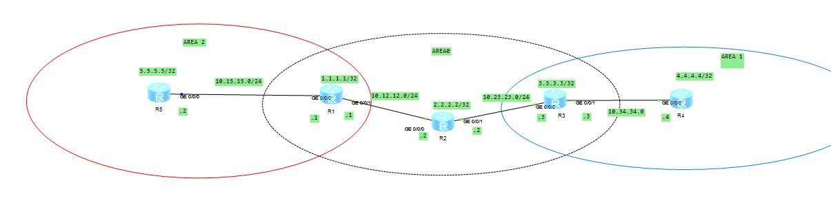
There are five routers: R1, R2, R3 in Area 0; R4 behind R3 in Area 1; R5 behind R1 in Area 2. R1 and R3 are ABRs.
| Router | Loopback0 (= Router ID) | Links |
|---|---|---|
| R1 | 1.1.1.1/32 | G0/0/1: 10.12.12.1/24 (R2), G0/0/0: 10.15.15.1/24 (R5) |
| R2 | 2.2.2.2/32 | G0/0/0: 10.12.12.2/24 (R1), G0/0/1: 10.23.23.1/24 (R3) |
| R3 | 3.3.3.3/32 | G0/0/0: 10.23.23.3/24 (R2), G0/0/1: 10.34.34.3/24 (R4) |
| R4 | 4.4.4.4/32 | G0/0/0: 10.34.34.4/24 (R3) |
| R5 | 5.5.5.5/32 | G0/0/0: 10.15.15.2/24 (R1) |
| Area | Routers | Networks |
|---|---|---|
| Area 0 | R1, R2, R3 | 10.12.12.0/24, 10.23.23.0/24, loopbacks |
| Area 1 | R3 (ABR), R4 | 10.34.34.0/24, 4.4.4.4/32 |
| Area 2 | R1 (ABR), R5 | 10.15.15.0/24, 5.5.5.5/32 |
The loopbacks of R1 and R3 are in Area 0, those of R4 and R5 in their own areas.
3. Configuration
Area 0 (R1, R2, R3)
The same pattern on all three: loopback, link IPs, then OSPF. R3 as an example:
system-view
sysname R3
interface LoopBack0
 ip address 3.3.3.3 32
 quit
interface GigabitEthernet0/0/0
 ip address 10.23.23.3 24
 quit
ospf 1 router-id 3.3.3.3
 area 0.0.0.0
  network 3.3.3.3 0.0.0.0
  network 10.23.23.0 0.0.0.255
  quit
 quit
The network lines use a wildcard mask, not a subnet mask: 0.0.0.255 for /24, 0.0.0.0 for a /32 loopback.
Area 1: making R3 an ABR, adding R4
On R3 I add Area 1 without touching the Area 0 settings. R3’s G0/0/1 interface now faces R4:
interface GigabitEthernet0/0/1
 ip address 10.34.34.3 24
 quit
ospf 1
 area 0.0.0.1
  network 10.34.34.0 0.0.0.255
  quit
 quit
On R4:
system-view
sysname R4
interface LoopBack0
 ip address 4.4.4.4 32
 quit
interface GigabitEthernet0/0/0
 ip address 10.34.34.4 24
 quit
ospf 1 router-id 4.4.4.4
 area 0.0.0.1
  network 4.4.4.4 0.0.0.0
  network 10.34.34.0 0.0.0.255
  quit
 quit
Area 2: making R1 an ABR, adding R5
On R1:
interface GigabitEthernet0/0/0
 ip address 10.15.15.1 24
 quit
ospf 1
 area 0.0.0.2
  network 10.15.15.0 0.0.0.255
  quit
 quit
On R5:
system-view
sysname R5
interface LoopBack0
 ip address 5.5.5.5 32
 quit
interface GigabitEthernet0/0/0
 ip address 10.15.15.2 24
 quit
ospf 1 router-id 5.5.5.5
 area 0.0.0.2
  network 5.5.5.5 0.0.0.0
  network 10.15.15.0 0.0.0.255
  quit
 quit
That’s all for the setup. The real work is in reading the outputs.
4. Verification
Who are the ABRs?
I look from R2, a pure Area 0 router, it should see both ABRs:
<R2>display ospf abr-asbr

         OSPF Process 1 with Router ID 2.2.2.2
         Routing Table to ABR and ASBR

 RtType      Destination     Area         Cost  Nexthop        Type
 Intra-area  1.1.1.1         0.0.0.0      1     10.12.12.1     ABR
 Intra-area  3.3.3.3         0.0.0.0      1     10.23.23.3     ABR
R1 and R3, exactly as I expected.
Area 0’s notebook: R2’s LSDB
<R2>display ospf lsdb

         OSPF Process 1 with Router ID 2.2.2.2
                 Link State Database

                         Area: 0.0.0.0
 Type      LinkState ID    AdvRouter       Age   Len   Sequence   Metric
 Router    2.2.2.2         2.2.2.2         1196  60    80000020   1
 Router    1.1.1.1         1.1.1.1         1535  48    80000016   1
 Router    3.3.3.3         3.3.3.3         1208  48    8000001C   0
 Network   10.12.12.2      2.2.2.2         1196  32    80000004   0
 Network   10.23.23.3      3.3.3.3         1208  32    80000003   0
 Sum-Net   10.34.34.0      3.3.3.3         164   28    80000004   1
 Sum-Net   5.5.5.5         1.1.1.1         80    28    80000001   1
 Sum-Net   4.4.4.4         3.3.3.3         180   28    80000001   1
 Sum-Net   10.15.15.0      1.1.1.1         1472  28    80000001   1
Let’s read this table line by line:
- Router LSAs (Type 1): Three of them, the three routers in Area 0. There are no Router LSAs for R4 and R5. R2 doesn’t know they exist.
- Network LSAs (Type 2): Two segments, two DRs. The LinkState ID is the DR’s interface IP:
10.12.12.2(DR R2),10.23.23.3(DR R3). There are two lines because there’s one DR per segment. The router that comes up first becomes DR, there’s no preemption. - Sum-Nets (Type 3): Four lines.
10.34.34.0and4.4.4.4are Area 1’s summary, Adv Router 3.3.3.3.10.15.15.0and5.5.5.5are Area 2’s summary, Adv Router 1.1.1.1. R2 sees these networks as “behind this ABR”.
So the topology stays inside the area. All that goes out is the information “you reach this network through this ABR”.
Area 1’s notebook: R4’s LSDB
<R4>display ospf lsdb

         OSPF Process 1 with Router ID 4.4.4.4
                 Link State Database

                         Area: 0.0.0.1
 Type      LinkState ID    AdvRouter       Age   Len   Sequence   Metric
 Router    4.4.4.4         4.4.4.4         225   48    80000006   1
 Router    3.3.3.3         3.3.3.3         1466  36    8000000C   1
 Network   10.34.34.3      3.3.3.3         1466  32    80000004   0
 Sum-Net   5.5.5.5         3.3.3.3         126   28    80000001   3
 Sum-Net   3.3.3.3         3.3.3.3         210   28    80000004   0
 Sum-Net   10.12.12.0      3.3.3.3         1254  28    80000003   2
 Sum-Net   2.2.2.2         3.3.3.3         1254  28    80000003   1
 Sum-Net   10.15.15.0      3.3.3.3         1518  28    80000001   3
 Sum-Net   1.1.1.1         3.3.3.3         1247  28    80000003   2
 Sum-Net   10.23.23.0      3.3.3.3         1296  28    80000003   1
R4 sees only two routers (itself and R3), the rest of the world comes as seven Sum-Nets and the Adv Router of all of them is 3.3.3.3. For R4, the world is a single door.
R5’s LSDB is the mirror image of this: two routers (1.1.1.1 and 5.5.5.5), everything else is a Sum-Net with Adv Router 1.1.1.1.
What does the Metric in a Sum-Net say?
The metric in a Sum-Net is the cost from the ABR to that network. Looking from R3’s eyes, using R4’s LSDB:
| Sum-Net | Metric | Path from R3 |
|---|---|---|
| 3.3.3.3 | 0 | R3 itself |
| 10.23.23.0 | 1 | directly connected |
| 2.2.2.2 | 1 | R3 → R2 |
| 10.12.12.0 | 2 | R3 → R2 → R1 side |
| 1.1.1.1 | 2 | R3 → R2 → R1 |
| 10.15.15.0 | 3 | behind R1 |
| 5.5.5.5 | 3 | R3 → R2 → R1 → R5 |
Since the cost of a Gigabit link is 1 with the default reference bandwidth, the numbers line up with the hop count.
The ABR’s two notebooks: R1’s LSDB
Since R1 is in both Area 0 and Area 2, there are two blocks in the output:
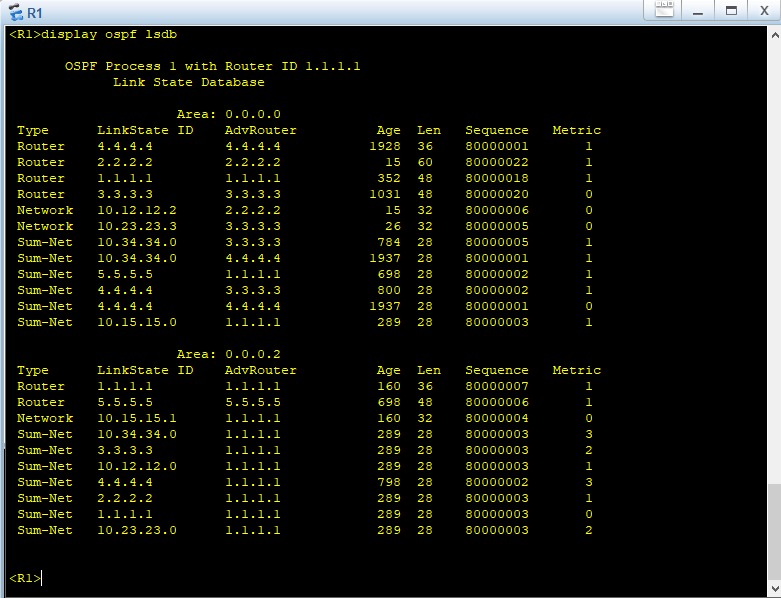
Three things caught my attention here:
Router 1.1.1.1appears twice. One in Area 0 (Len 48, Seq 80000016), the other in Area 2 (Len 36, Seq 80000005). The ABR generates a separate Router LSA for each area, meaning it keeps a separate notebook for each of its legs.4.4.4.4and10.34.34.0in Area 2 didn’t come directly from Area 1. R1 never saw R4’s Router LSA. It learned this information from the Sum-Net that R3 pushed into Area 0 and pushed it again into its own Area 2. The metric shows this too: the4.4.4.4that R3 gives in Area 0 has metric 1, the one R1 gives into Area 2 has 3 (R1→R2 1, R2→R3 1, plus R3’s 1). So between areas OSPF carries distance, not topology, it works like distance-vector. That’s the real reason for the Area 0 rule: since summaries always pass through the backbone, no loop forms.- Local networks don’t become Sum-Nets in their own area. In Area 2 there’s no Sum-Net for
10.15.15.0, because it already knows it from the Router/Network LSA. A Sum-Net is generated only for information “coming from another area”.
Routing table: R4’s OSPF routes
<R4>display ip routing-table protocol ospf
Route Flags: R - relay, D - download to fib
------------------------------------------------------------------------------
Public routing table : OSPF
         Destinations : 7        Routes : 7

OSPF routing table status : <Active>
         Destinations : 7        Routes : 7

Destination/Mask    Proto   Pre  Cost      Flags NextHop         Interface

        1.1.1.1/32  OSPF    10   3           D   10.34.34.3      GigabitEthernet0/0/0
        2.2.2.2/32  OSPF    10   2           D   10.34.34.3      GigabitEthernet0/0/0
        3.3.3.3/32  OSPF    10   1           D   10.34.34.3      GigabitEthernet0/0/0
        5.5.5.5/32  OSPF    10   4           D   10.34.34.3      GigabitEthernet0/0/0
      10.12.12.0/24 OSPF    10   3           D   10.34.34.3      GigabitEthernet0/0/0
      10.15.15.0/24 OSPF    10   4           D   10.34.34.3      GigabitEthernet0/0/0
      10.23.23.0/24 OSPF    10   2           D   10.34.34.3      GigabitEthernet0/0/0
- Seven routes = seven Sum-Nets. Every Sum-Net in the LSDB went into the table as a route.
- The next hop of all of them is
10.34.34.3(R3). Whatever destination R4 goes to, it uses the single door. - Cost = R4’s link cost to R3 (1) + the Sum-Net metric. For
5.5.5.5, 1 + 3 = 4. - Pre 10: On Huawei, OSPF’s preference value is 10. On Cisco this is 110.
4.4.4.4and10.34.34.0are not in the list, because they are R4’s own connected networks.
R5’s table is the mirror by the same logic: all via 10.15.15.1 (R1), costs 1 from R1, 2 from R2, 3 from R3, 4 from R4.
The route type: display ospf routing
Huawei doesn’t mark inter-area routes separately in the table, but this command shows the type:
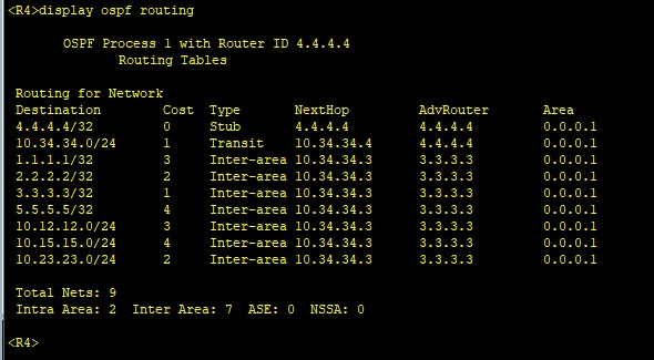
Intra Area: 2 are from its own area, Inter Area: 7 from other areas. In all of them AdvRouter is 3.3.3.3.
Connectivity and path test
From R4 to R5, loopback to loopback:
<R4>ping -a 4.4.4.4 5.5.5.5
  PING 5.5.5.5: 56  data bytes, press CTRL_C to break
    Reply from 5.5.5.5: bytes=56 Sequence=1 ttl=252 time=40 ms
    Reply from 5.5.5.5: bytes=56 Sequence=2 ttl=252 time=20 ms
    Reply from 5.5.5.5: bytes=56 Sequence=3 ttl=252 time=50 ms
    Reply from 5.5.5.5: bytes=56 Sequence=4 ttl=252 time=40 ms

  --- 5.5.5.5 ping statistics ---
    4 packet(s) transmitted
    4 packet(s) received
    0.00% packet loss
    round-trip min/avg/max = 20/37/50 ms
ttl=252: the reply leaves R5 with 255 and passes three routers on the way (R1, R2, R3), so it arrives as 252. Consistent with the hop count.
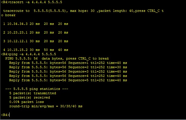
The path is R3 → R2 → R1 → R5. Traffic from Area 1 to Area 2 doesn’t go directly, it goes through Area 0.
5. Where I got stuck
The Router ID wasn’t what I expected
R4’s OSPF header said Router ID 10.34.34.4, not 4.4.4.4. I had opened ospf 1 before configuring the loopback, so the router picked one of the interface IPs. If the Router ID isn’t given by hand, it looks in order at the highest loopback IP, and if there’s no loopback, the highest interface IP. This choice is made when the process starts and stays even if the IP changes later. That’s why I now always give the ID by hand:
ospf 1 router-id 4.4.4.4
To make the new ID take effect while the process is running, you need to reset the process.
router-id didn’t work inside OSPF
Out of Nokia habit, I typed ospf 1, went inside and typed router-id 4.4.4.4, and it wasn’t accepted. In Huawei VRP there’s no such command in the OSPF view. There are two ways: in a single line when opening the process, ospf 1 router-id 4.4.4.4, or the general router id 4.4.4.4 in system-view.
reset ospf 1 process wasn’t recognized
The command itself was right, but I was typing it in the wrong place. On Huawei, reset commands work in user view (<R4>), not inside [R4]. I first type return to get out, then:
<R4>reset ospf 1 process
Warning: The OSPF process will be reset. Continue? [Y/N]:y
The same rule applies to save.
4.4.4.4 and 5.5.5.5 weren’t in the LSDB
When I first looked, R2’s LSDB only had the link networks (10.34.34.0, 10.15.15.0), not the loopbacks. The cause was that I never configured the loopback on R4 and R5, in other words I confused the Router ID with the address. The Router ID is only the router’s identity. For “there’s a network called 5.5.5.5” to show up in the LSDB, that IP has to be on an interface and given to OSPF with a network line. After I added the loopback and the network 5.5.5.5 0.0.0.0 line, the Sum-Nets arrived.
6. Virtual-link: an area that can’t connect to Area 0
There’s an exception path to the Area 0 rule. If an area can’t physically connect to Area 0, a virtual link to Area 0 can be built across the area in between (the transit area). The physical cable stays the same, but OSPF treats those two routers as Area 0 neighbors.
I tried it in the lab between R3 and R4. The command is written inside the transit area that the Hellos will cross, and it identifies the other end by its Router ID:
On R3:
ospf 1
 area 0.0.0.1
  vlink-peer 4.4.4.4
On R4:
ospf 1
 area 0.0.0.1
  vlink-peer 3.3.3.3
It has to be entered on both ends. On my first try I had written the command inside Area 0:
[R3-ospf-1-area-0.0.0.0]vlink-peer 4.4.4.4
Error: Virtual-link can not be configured in backbone area.
Since the virtual link is used to extend Area 0, it’s written not inside Area 0 but inside the transit area (Area 1 here). R3 finds the path to the other end from Area 1’s internal routing. That’s why it mattered that R4’s loopback was advertised in Area 1.
When I wrote the command in the right place, the log showed the same transitions as an ordinary neighborship:
VirtualLinkNeighborAddress=4.4.4.4, NeighborEvent=HelloReceived, PreviousState=Down, CurrentState=Init
VirtualLinkNeighborAddress=4.4.4.4, NeighborEvent=2WayReceived, PreviousState=Init, CurrentState=ExStart
VirtualLinkNeighborAddress=4.4.4.4, NeighborEvent=NegotiationDone, PreviousState=ExStart, CurrentState=Exchange
The virtual link also moves on to LSDB exchange like an ordinary OSPF neighborship.
Rules:
- The transit area can’t be a stub. Since LSAs pass through that area, it has to carry the full LSDB.
- Fragile: The virtual link depends on the physical line of the transit area. If that line goes, the virtual link goes down too.
- Not the first choice. The right design is to really connect the area to Area 0 through an ABR. A virtual link is usually used as a temporary fix, or to reconnect the backbone when a link breaks.
7. Summary
- Areas split the network into regions: the SPF calculation gets smaller, the LSDB gets smaller, summarization becomes possible.
- An ABR is a router with one leg in Area 0. It keeps a separate notebook (LSDB) for each area.
- Area 0 is mandatory: information between areas is carried only through the backbone, with Type 3 (Sum-Net) LSAs.
- Between areas OSPF carries distance, not topology, like distance-vector. That’s why there are no loops.
- A router doesn’t see the details of an outside area: in the LSDB there are only Sum-Nets, and the Adv Router of all of them is the ABR.
- In the routing table, cost = the cost to the ABR you’re attached to + the Sum-Net metric, and you see the route type (
Intra-area,Inter-area) withdisplay ospf routing. - The Router ID is an identity, the loopback is an address. A
networkline is required for a network to show up in the LSDB. - On Huawei,
resetandsaveare in user view, androuter-idis written asospf 1 router-id X.X.X.X. - A virtual link is a patch for an area that can’t connect to Area 0, and it’s written inside the transit area.