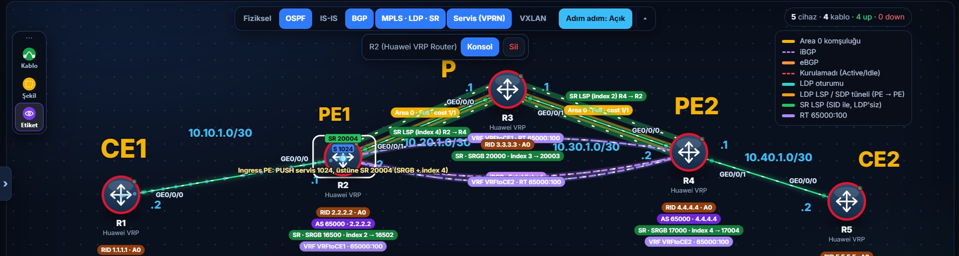
Topology: R1 = CE1, R2 = PE1, R3 = P, R4 = PE2, R5 = CE2. The customer LANs sit on Loopback1 of the CEs (192.168.1.1/24 and 192.168.2.1/24).
1. What I’m trying to do
No LDP in the core. Segment Routing distributes the labels through OSPF, and a customer L3VPN sits on top. The goal is simple: ping from CE1’s LAN to CE2’s LAN.
I explained the concept in a separate post. This one is just the commands and the places I got stuck. I did the same thing on Nokia here, where a similar small trap showed up.
I shortened the configuration blocks: I only show the parts that matter here, and you need to fill in the physical interface IPs from the plan table. A real Huawei device may need extra commands depending on platform and version, and some versions (the ones with two-stage configuration) also need a commit to activate what you typed. The customer LANs are not real LANs either, they are the Loopback1 addresses on the CEs acting as endpoints.
I first tried this in eNSP. The AR image doesn’t know the segment-routing command, and NE40E needs a separately imported package and froze on my machine. So I built it from an empty topology in this site’s simulation page. All outputs are from the simulator.
2. Plan
| Router | Role | Loopback0 | SID index | Links |
|---|---|---|---|---|
| R1 | CE1 | 1.1.1.1/32 | - | GE0/0/0 10.10.1.2/30 |
| R2 | PE1 | 2.2.2.2/32 | 2 | GE0/0/0 CE1 (10.10.1.1/30), GE0/0/1 R3 (10.20.1.2/30) |
| R3 | P | 3.3.3.3/32 | 3 | 10.20.1.1/30 and 10.30.1.1/30 |
| R4 | PE2 | 4.4.4.4/32 | 4 | R3 (10.30.1.2/30), GE0/0/1 CE2 (10.40.1.1/30) |
| R5 | CE2 | 5.5.5.5/32 | - | GE0/0/0 10.40.1.2/30 |
AS 65000 (iBGP between the PEs). I named the VPN instances VRFtoCE1 and VRFtoCE2; the name only matters inside the device. Both PEs use RD 65000:100 and RT 65000:100 (import and export). I left the SRGBs different per router: R2 starts at 16500, R3 at 20000, R4 at 17000. A label is the SRGB base plus the index, so R2’s own label is 16502, R3’s is 20003, R4’s is 17004.
3. Configuration
Order: IP, OSPF and SR first (the core), then MP-BGP, then the VPN instance and the PE-CE side.
3.1 Core: IP, OSPF, SR (example for R2)
system-view
sysname R2
interface LoopBack0
 ip address 2.2.2.2 32
quit
mpls lsr-id 2.2.2.2
mpls
quit
segment-routing
quit
ospf 1 router-id 2.2.2.2
 opaque-capability enable
 segment-routing mpls
 segment-routing global-block 16500 17499
 area 0
  network 2.2.2.2 0.0.0.0
  network 10.20.1.0 0.0.0.3
 quit
quit
interface LoopBack0
 ospf prefix-sid index 2
quit
Pick the SRGB end value to fit your own plan. There is no mpls ldp on the interfaces, I didn’t even type mpls there. R3 and R4 get the same with their own addresses, SRGBs and indexes (3 and 4).
Before going further, check three things: display ospf peer brief (are the adjacencies Full), display segment-routing prefix mpls forwarding (are the other routers’ SIDs there) and ping -a 2.2.2.2 4.4.4.4. If the ping works, the loopbacks are ready for BGP.
3.2 MP-BGP: only R2 and R4 talk
bgp 65000
 router-id 2.2.2.2
 peer 4.4.4.4 as-number 65000
 peer 4.4.4.4 connect-interface LoopBack0
 ipv4-family vpnv4
  peer 4.4.4.4 enable
 quit
quit
On R4 it is router-id 4.4.4.4 and peer 2.2.2.2. P (R3) never joins BGP. It knows nothing about customer routes, it just looks at the labels and forwards.
3.3 VPN instance and PE-CE (R2)
ip vpn-instance VRFtoCE1
 ipv4-family
  route-distinguisher 65000:100
  vpn-target 65000:100 export-extcommunity
  vpn-target 65000:100 import-extcommunity
 quit
quit
interface GigabitEthernet0/0/0
 ip binding vpn-instance VRFtoCE1
 ip address 10.10.1.1 255.255.255.252
quit
ip route-static vpn-instance VRFtoCE1 192.168.1.0 255.255.255.0 10.10.1.2
bgp 65000
 ipv4-family vpn-instance VRFtoCE1
  import-route static
 quit
quit
Order matters: ip binding comes before the IP address, because binding deletes any address already on the interface. The CEs only have an address and a static route to the other LAN. R4 is the same with VRFtoCE2, GE0/0/1, 10.40.1.1 and 192.168.2.0.
4. Where I got stuck
This is the real part of the post, because a few different things piled up.
I put a default route on the PE. On my first try I wrote a 0.0.0.0/0 static route inside the VPN instance, next to import-route static. Result: BGP carried the default instead of the LAN, and the remote PE never saw the specific LAN prefix. The fix: write the LAN with its own prefix on the PE and delete the default. (In this simulator undo ip route-static vpn-instance ... also wants the next hop, it won’t delete without it.)
I hadn’t enabled the VPNv4 family on R4. The BGP session showed Established, but R4’s VPNv4 table had no routes from the other PE:
[R4] display bgp vpnv4 all routing-table
 Total number of routes from all PE: 0
 Route Distinguisher: 65000:100

 *>    192.168.2.0/24     0.0.0.0         0                    0      ?
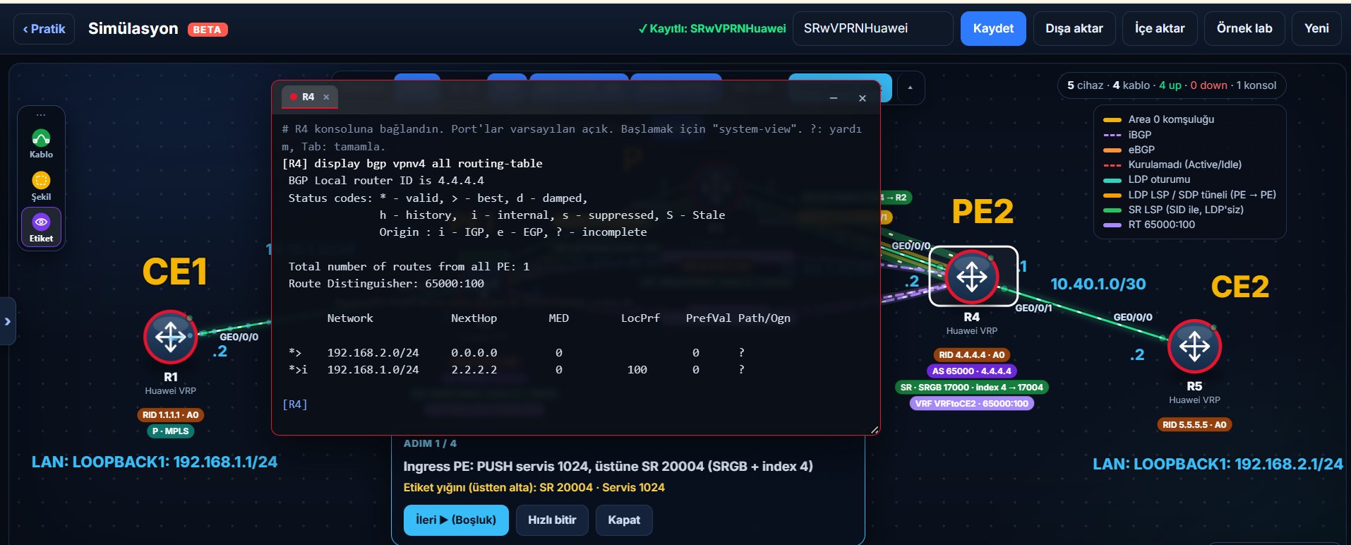
Only its own LAN. R2’s VPNv4 side was fine. When I ran display current-configuration configuration bgp, R4 had no ipv4-family vpnv4 block at all. peer 2.2.2.2 enable had only been entered under the unicast family. The normal BGP session comes up, but VPN routes don’t flow because the VPNv4 address family isn’t enabled on both sides. There is a distinction here: display bgp peer shows the general session, display bgp vpnv4 all peer shows the neighbors in the VPNv4 family. On a real VRP I wouldn’t expect to see that neighbor as Established in the VPNv4 output if the family isn’t enabled, so the simulator may not behave exactly like a real device here. After I opened the VPNv4 block and entered peer 2.2.2.2 enable, the counter went to 1, but the table still showed only its own LAN.
The tunnel policy. The counter was 1 but the route still wasn’t in the table. The reason: nothing told the VPN instance which tunnel to use to reach the next hop (2.2.2.2) of the received VPN route. A core with LDP usually doesn’t need this, because by default classic MPLS LSPs (an LDP LSP in my lab) are used. For an SR-MPLS tunnel to be chosen, depending on platform and software version you may need a tunnel policy or an SR tunnel preference setting, so the VPN instance has to be told explicitly.
To be honest about one thing: on a real VRP I think a received VPNv4 route would show in the BGP table but not get installed in the VRF routing table, because it can’t be resolved to a usable transport tunnel, but I haven’t tried it on a real device. The simulator doesn’t show the route at all, only the counter goes up. The practical lesson: seeing a route in BGP and having it installed in the VRF are two different tables, and you have to look at both.
4.1 The fix
On both PEs:
tunnel-policy SRP
 tunnel select-seq sr-lsp load-balance-number 1
quit
ip vpn-instance VRFtoCE1
 ipv4-family
  tnl-policy SRP
 quit
quit
On R4 the instance name is VRFtoCE2. The three lines do this: tunnel-policy SRP opens a rulebook (the name is free), tunnel select-seq sr-lsp writes “pick the SR tunnel, one path is enough” into it, and tnl-policy SRP attaches the rulebook to the VPN instance. If you don’t attach it, the rulebook exists but nobody uses it.
Huawei’s own example shows another way: tunnel-prefer segment-routing under the global segment-routing. I didn’t try that one, this post uses the policy way.
4.2 Four separate stages
This lab taught me that the following are four different things, each with its own check.
| Stage | Meaning | Where to look |
|---|---|---|
| 1 | The BGP session is up | display bgp peer |
| 2 | The VPNv4 route was learned | display bgp vpnv4 all routing-table |
| 3 | The route was installed in the VRF table | display ip routing-table vpn-instance VRFtoCE1 |
| 4 | Traffic is carried over MPLS | CE to CE ping |
Each mistake in this post got stuck at a different stage: the first two at stage 2, the missing tunnel policy at stage 3. You can also check the SR tunnel itself with display tunnel-info all, the OSPF adjacency with display ospf peer brief and the SIDs with display segment-routing prefix mpls forwarding.
5. Outputs that show it works
R4’s VPNv4 table now has two routes. One is its own LAN, the other is 192.168.1.0/24 from R2 with next hop 2.2.2.2:
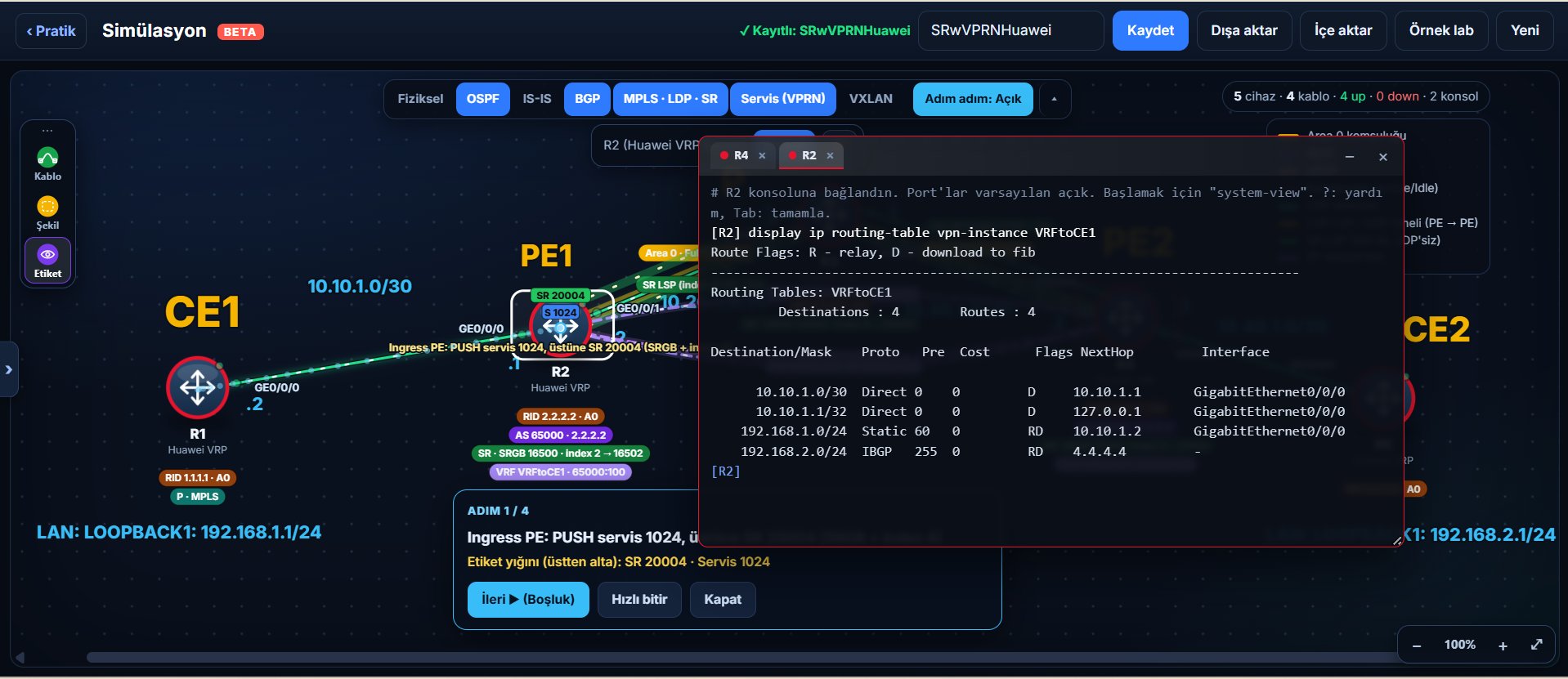
R2’s VPN instance table now gets the remote LAN too. The last line is IBGP, next hop 4.4.4.4:
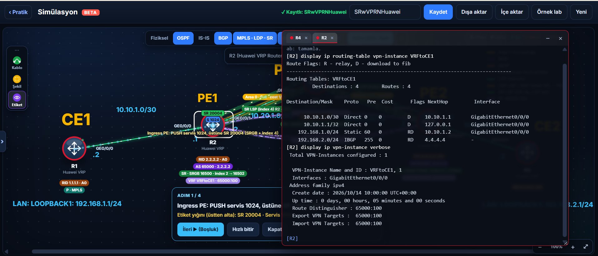
In the same console, the RD and RTs of the VPN instance. Both PEs say 65000:100:
Finally, CE to CE ping. From R5 to R1’s LAN, sourced from my own LAN address:
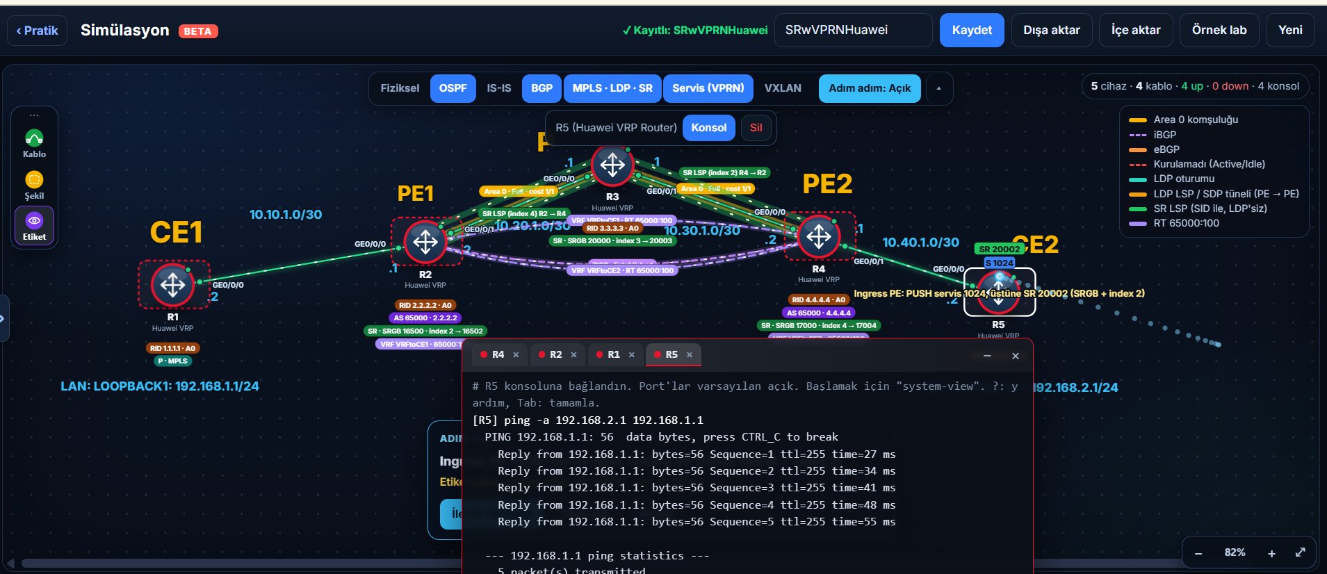
The topology view also shows the label stack. On the packet leaving R2 the top label is the SR label 20004 and below it the service label 1024. It is 20004 because the neighbor R3’s SRGB starts at 20000 and the target index is 4. When traffic goes from R5 to R1, the label is added by the ingress PE R4, not by R5 (R5 is a CE and does no label work). R4 puts the label for R2’s Prefix-SID. The first neighbor to receive the packet is R3, so R3’s SRGB (20000) and R2’s index (2) are used: 20002 on top.
6. Small things I noticed afterwards
To ping a CE from a PE you need ping -vpn-instance VRFtoCE1 10.10.1.2. A plain ping looks at the global table and that route isn’t there, because the PE-CE interface is bound to the VPN.
I used the same RD on both PEs. It caused no problem in this lab because each LAN lives on only one PE. If the same prefix will be advertised from different PEs, a different RD per PE matters, because BGP can then carry those paths as separate VPNv4 routes. Having the same RT on both sides is correct.
7. Try it yourself
The same scenario is on the site in two versions:
- Short version: the core, the VPN and MP-BGP come ready, the tunnel policy is missing.
- From-scratch version: the routers start empty and you build everything.
The whole series: MPLS from scratch.