1. Why this post?
In the VPLS post we made two distant sites talk as if they were plugged into the same switch. The customer’s L2 frame was carried with an MPLS label. VXLAN does the same job. The only difference is that it carries the frame not with an MPLS label, but by putting it inside an ordinary IP/UDP packet. There’s no MPLS or LDP underneath, IP reachability is enough.
This post is the first post of the “VXLAN from Scratch” series. Here I’ll set up the logic without tying it to any vendor. In the next posts I’ll do the same setup on Nokia, Huawei and Cisco one by one. At the very end I’ll move on to EVPN, which distributes MAC addresses with BGP.
At the end of the post there is a ready-made lab that opens in your browser. Three different vendors talk in the same VNI, and you can see the packet’s VXLAN header step by step.
2. The problem: the network is L3, the application wants the same L2
In modern data centers the network is usually built as spine-leaf. There is a leaf switch on top of every rack, and the leaves are connected to the spines. Every link in between is a separate IP network, with OSPF or BGP running on top. So the body of the network is fully L3. The reason is simple: in L3 there are no loops, no STP, and all links can be used at the same time (ECMP).
But applications still want L2:
- When a virtual machine moves from Rack 1 to Rack 2, you want its IP address to stay the same.
- The servers in a cluster need to be in the same subnet.
- You want a separate L2 segment per customer or application, but the VLAN field is 12 bits. At most 4094 segments.
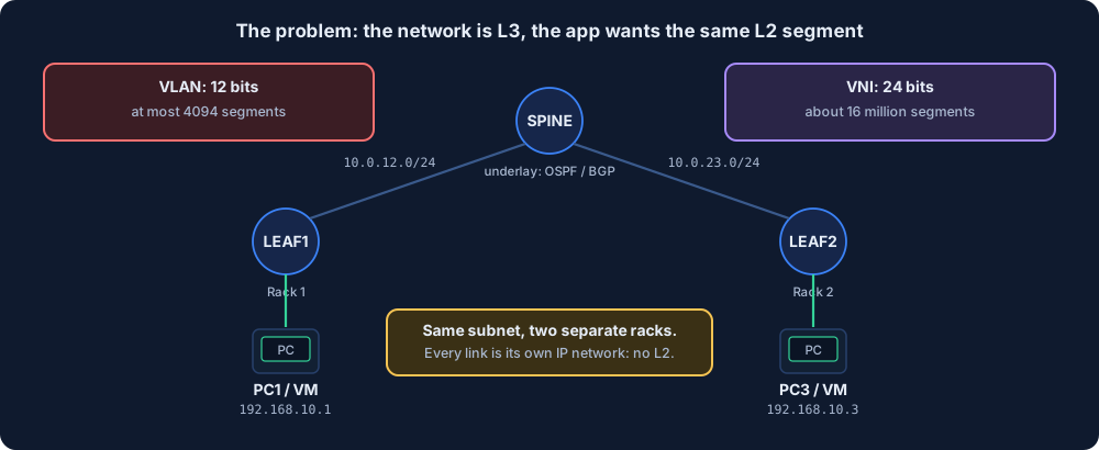
VXLAN’s answer is: “Let the body stay L3. Let’s put the L2 frame into an IP packet and carry it to the other rack.” To separate segments during this transport, a 24-bit number is used: the VNI. 24 bits means about 16 million segments.
3. Analogy: the internal memo and the courier envelope
A company has two buildings: Building A and Building B. Inside a building, everyone sends each other internal memos. The memo only says “Ayşe, 5th floor”. The building’s internal mail system understands this. But the couriers in the city don’t recognize an address like “Ayşe, 5th floor”.
When someone in Building A writes a memo to Ayşe in Building B, this happens:
- The memo goes to Building A’s mail room.
- The mail room puts the memo into a courier envelope without opening it. It writes two things on the envelope: the receiving building (Building B) and the department code (5010).
- The couriers in the city only look at the building address on the envelope. They don’t open it, they don’t know Ayşe.
- Building B’s mail room opens the envelope, looks at the department code and gives the memo to the right floor.
- Ayşe receives the memo. She has no idea it traveled across the city.
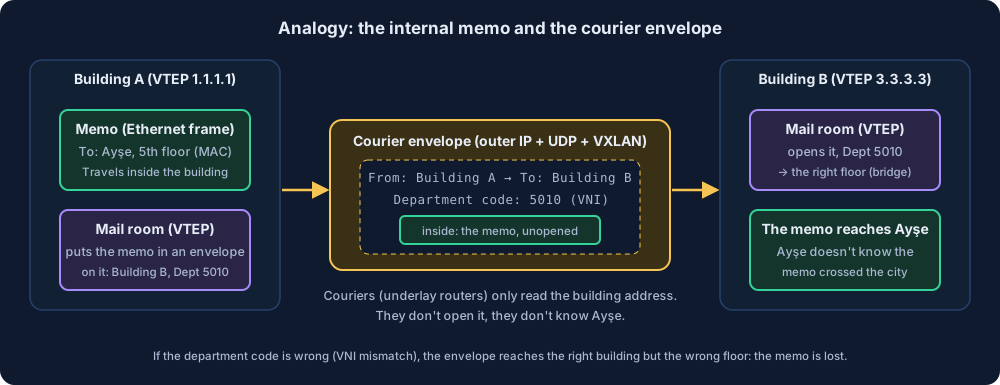
Let’s match them:
| Analogy | VXLAN |
|---|---|
| Internal memo | The original Ethernet frame (sent by the PC) |
| “Ayşe, 5th floor” | Destination MAC address |
| Mail room | VTEP (VXLAN Tunnel End Point) |
| Building address | The VTEP’s IP address (usually a loopback) |
| Department code | VNI (VXLAN Network Identifier) |
| Couriers in the city | Underlay routers |
| Internal mail inside the building | Overlay: the L2 segment the PCs see |
The analogy also has a trap: if the department code is written wrong, the envelope goes to the right building but is delivered to the wrong floor. In VXLAN too, if the VNI is different on the two ends, the tunnel looks up but the ping doesn’t go through. I’ll come back to this in the lab.
4. Encapsulation: what does the packet look like?
The VTEP doesn’t touch the frame coming from the PC. It adds four headers in front of it:
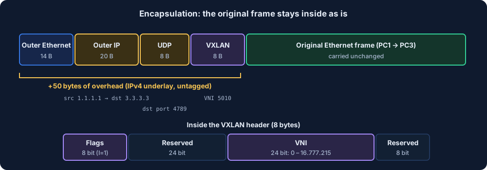
| Header | Size | What’s inside |
|---|---|---|
| Outer Ethernet | 14 bytes | The MAC of the next underlay router |
| Outer IP | 20 bytes | Source: this VTEP (1.1.1.1), destination: the remote VTEP (3.3.3.3) |
| UDP | 8 bytes | Destination port 4789 |
| VXLAN | 8 bytes | Flags and the 24-bit VNI |
| Original frame | unchanged | The Ethernet frame PC1 sent, as is |
Two details matter:
- The UDP source port is not fixed. The VTEP picks it with a hash of the inner frame’s headers. Because underlay routers also look at UDP ports when load-balancing (ECMP), different flows are spread over different paths. The destination port is always 4789.
- There are 50 bytes of overhead. If the PC sends a 1500-byte packet, the packet becomes 1550 bytes in the underlay. If the MTU of the underlay links can’t carry this, big packets are dropped. I open this up in section 8.
5. Terms: VTEP, VNI, underlay, overlay
| Term | What it means |
|---|---|
| VTEP | The device that wraps the frame into VXLAN and unwraps it. It can be a leaf switch, a router or a virtual switch inside a server |
| VNI | 24-bit segment number. Same VNI = same L2 segment. Think of it as VLAN’s big brother |
| Underlay | The network that lets VTEPs reach each other over IP. Built with OSPF, IS-IS or BGP. It knows nothing about VXLAN |
| Overlay | The virtual L2 network formed on top of the VXLAN tunnels. The PCs see this |
| NVE | Network Virtualization Edge. Some vendors give this name to the VTEP’s logical interface (interface nve1, interface Nve1) |
| Bridge domain | The virtual switch inside the VTEP. It is bound to a VNI, and access ports are attached to it |
In short, on every VTEP you set up three things: a source address (usually a loopback), a bridge (bridge domain or VPLS) and binding this bridge to a VNI. On top of that you give it the list of remote VTEPs.
6. The packet’s journey
PC1 (Rack 1) and PC3 (Rack 2) are in the same subnet, in the same VNI. PC1 pings PC3:
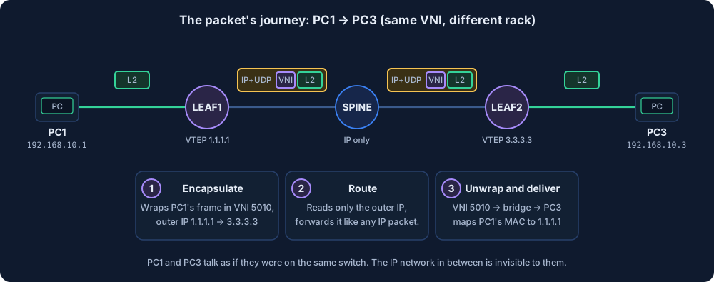
- LEAF1 (encapsulate): The frame from PC1 enters the bridge bound to VNI 5010. If the destination MAC has been learned behind the remote VTEP, LEAF1 wraps the frame into VXLAN. Outer IP: 1.1.1.1 → 3.3.3.3.
- SPINE (route): What arrives is an ordinary IP packet. It looks at the route to 3.3.3.3 and forwards it. It doesn’t know there’s an Ethernet frame inside, and it doesn’t need to.
- LEAF2 (unwrap and deliver): Recognizes the packet arriving on UDP 4789 and strips the headers. It looks at VNI 5010 and gives the frame to that bridge. On the way it also notes what it learned: “PC1’s MAC is behind 1.1.1.1.”
From the SPINE’s point of view, the only thing it sees is UDP traffic between 1.1.1.1 and 3.3.3.3. The customer’s MACs, VLANs and IPs never reach the spine. Just like the P router in MPLS that looks at nothing but the label.
7. What if I don’t know the destination? Flood and learn
Above I said “if the destination MAC has been learned”. So what happens to the first packet? PC1 first sends an ARP: “who has 192.168.10.3?” This is a broadcast. The VTEP needs to know who to send it to.
This kind of traffic is called BUM: Broadcast, Unknown unicast, Multicast. VXLAN has two methods for BUM:
- Multicast underlay: Every VNI is mapped to a multicast group, and the VTEP sends BUM packets to that group. PIM is needed in the underlay. VXLAN’s original design (RFC 7348) is based on this.
- Head-end replication (ingress replication): You give the VTEP the list of remote VTEPs by hand. It sends the BUM packet as a separate unicast copy to every VTEP in the list. No multicast is needed in the underlay.
In this post and in the simulator I use the second one, because it’s the easiest to set up.
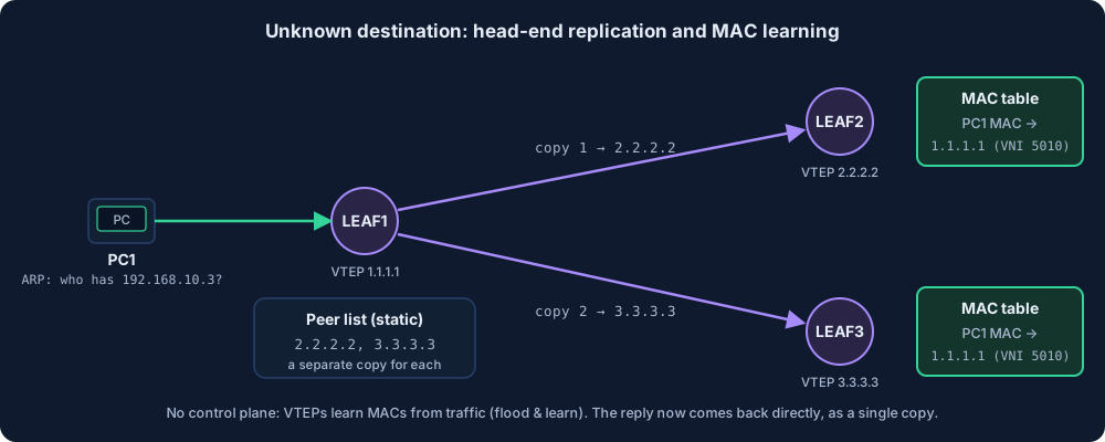
The flow is:
- LEAF1 copies PC1’s ARP separately to every VTEP in its list (2.2.2.2 and 3.3.3.3).
- Every VTEP that receives a copy learns PC1’s MAC as “behind 1.1.1.1”.
- PC3 replies. Since LEAF3 now knows where PC1 is, it sends the reply as a single copy directly to 1.1.1.1.
This is called flood and learn: there’s no control plane, everything is learned from traffic. In VPLS, MACs were learned this way too.
This method has two weak sides. As the number of VTEPs grows, every BUM packet is copied that many times. You also manage the peer list by hand on every VTEP: with 50 leaves you write 49 addresses on each one. EVPN solves exactly this problem: VTEPs learn each other and the MAC addresses with BGP. That’s the topic of the last post in the series.
8. The MTU trap
The most classic VXLAN failure is MTU. The symptom: ping works, SSH opens, but the connection hangs while copying a file or loading a web page. Small packets get through, big ones don’t.
The cause is the 50 bytes from section 4. The PCs send 1500 bytes, the packet becomes 1550 bytes in the underlay. If the MTU of the underlay links is 1500, these packets don’t fit. In practice there are two fixes:
- Increase the underlay MTU: Data centers usually use 9000 or 9216 (jumbo). This is the cleanest fix.
- Decrease the PCs’ MTU: Something like 1450. Not preferred much, because every end device has to be configured.
The simulator doesn’t calculate MTU. So you can’t see this trap there. In a real lab you can test it by giving the ping command a big size and the “don’t fragment” (DF) flag.
9. Side by side with VPLS
Since you know VPLS, a comparison makes things easier:
| VPLS | VXLAN | |
|---|---|---|
| What does it carry? | L2 frame | L2 frame |
| Inside what? | MPLS label | IP + UDP + VXLAN header |
| What’s needed underneath? | MPLS + LDP (or RSVP / SR) | Only IP reachability |
| Tunnel | Pseudowire (over an SDP) | VTEP to VTEP |
| Segment number | Service ID / VC-ID | VNI (24 bits) |
| How are the ends found? | T-LDP or BGP | Static list, multicast or EVPN |
| MAC learning | From traffic (data plane) | From traffic with static, with BGP in EVPN |
| Loop prevention | Mesh-SDP split horizon | Traffic from a VTEP is not sent back to another VTEP |
| Where is it common? | Service provider core | Data center fabric (more and more in SP too) |
In short: VPLS’s logic stays exactly the same, only the carrier changes from MPLS to IP. That’s why someone who understands VPLS already knows half of VXLAN.
10. The same setup on three vendors
I’m putting the same job side by side on three vendors: LEAF1’s loopback is 1.1.1.1, the remote VTEP is 3.3.3.3, the port the PC is connected to is untagged, bridge 10, VNI 5010. I’m assuming the underlay (OSPF and the loopbacks) is ready.
Cisco IOS-XE (CSR1000v / Catalyst 8000v):
interface GigabitEthernet0/1
 no shutdown
 service instance 10 ethernet
  encapsulation untagged
!
bridge-domain 10
 member vni 5010
 member GigabitEthernet0/1 service-instance 10
!
interface nve1
 no shutdown
 source-interface Loopback0
 member vni 5010
  ingress-replication 3.3.3.3
Huawei VRP (CloudEngine):
bridge-domain 10
 vxlan vni 5010
#
interface GigabitEthernet0/0/1.1 mode l2
 encapsulation untag
 bridge-domain 10
#
interface Nve1
 source 1.1.1.1
 vni 5010 head-end peer-list 3.3.3.3
Nokia SR OS (classic CLI):
configure service vpls 10 customer 1 create
    sap 1/1/2 create
        no shutdown
    exit
    vxlan instance 1 vni 5010 create
        egr-vtep 3.3.3.3 create
        exit
    exit
    no shutdown
All three are made of the same four parts, only the names are different:
| Part | Cisco | Huawei | Nokia |
|---|---|---|---|
| Bridge | bridge-domain 10 | bridge-domain 10 | vpls 10 |
| Bridge ↔ VNI | member vni 5010 | vxlan vni 5010 | vxlan instance 1 vni 5010 |
| Access port | service instance + member ... service-instance | interface X.1 mode l2 + bridge-domain 10 | sap 1/1/2 |
| VTEP source | source-interface Loopback0 | source 1.1.1.1 | system address (default) |
| Remote VTEPs | ingress-replication 3.3.3.3 | head-end peer-list 3.3.3.3 | egr-vtep 3.3.3.3 |
Verification commands:
| Question | Cisco | Huawei | Nokia |
|---|---|---|---|
| Are the tunnels up? | show nve peers | display vxlan tunnel | show service vxlan |
| Which bridge is the VNI in? | show nve vni | display vxlan vni | show service id 10 vxlan |
| Where were the MACs learned from? | show bridge-domain 10 | display mac-address bridge-domain 10 | show service id 10 fdb detail |
A few honest notes:
- Cisco: This syntax is for IOS-XE routers (CSR1000v, Catalyst 8000v). Classic IOS (like IOSv in GNS3) has no VXLAN. Nexus switches use NX-OS and the commands are different (
feature nv overlay,vn-segment). - Huawei: VXLAN runs on CloudEngine (CE) switches. In eNSP you need the CE12800 image for this, AR routers have no VXLAN commands. On a real CE the interface names look like
10GE1/0/1. - Nokia: The
vxlan instance ... egr-vtepsyntax is from newer releases. On some older releases you writevxlan vni 5010 create. I’ll try in my own lab what static VXLAN looks like on my older vSIM image in GNS3, and write it up in the Nokia post. - Simulator: For convenience, these commands work on the routers in the simulator. The interface names are the simulator’s names too. Change them to the names on the real device according to the notes above.
11. Try it in the simulator
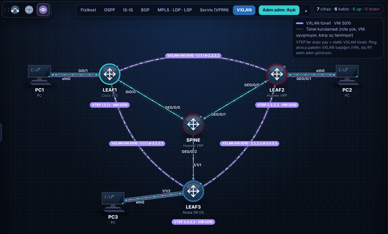
On the Simulation page (Turkish UI), open the ready-made lab Yeni → “VXLAN: üç vendor, tek VNI” (three vendors, one VNI). Cisco, Huawei and Nokia leaves are in the same VNI 5010. The spine is Huawei, the underlay is OSPF. Because static VXLAN is a standard, the VTEPs don’t know each other’s brand.
When you open the VXLAN tab at the top, you see the tunnels between the VTEPs and which VNI they carry on the map:
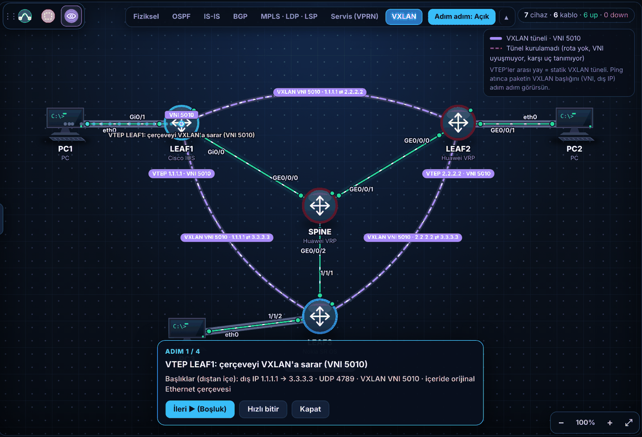
If you turn on Adım adım (step by step) mode and ping from PC1 to PC3, the packet stops on every cable. The panel shows which headers are on the packet at that moment:
A few ideas to try:
- Start with
PC1> ping 192.168.10.3. Then look at the verification commands above on the LEAFs. Check behind which VTEP the PCs appear in the MAC table. - Break it and fix it: On LEAF2 (Huawei), make the VNI 5020: under
bridge-domain 10,vxlan vni 5020, and underinterface Nve1,vni 5020 head-end peer-list 1.1.1.1 3.3.3.3.display vxlan tunnelstill shows both tunnels asup, because there are routes to the remote VTEPs in the underlay. But the ping from PC1 to PC2 doesn’t go through. On the map the tunnels turn red and show the reason: the VNI doesn’t match. The “wrong floor” trap from section 3 is exactly this: the envelope goes to the right building and is delivered to the wrong floor. - Forget one side: On LEAF1 (Cisco), under
interface nve1→member vni 5010, typeno ingress-replication 3.3.3.3. Now LEAF3 keeps LEAF1 in its list, but LEAF1 doesn’t know LEAF3. In this case the simulator doesn’t let PC1 and PC3 talk. On real devices the behavior can vary by vendor: some drop packets from a VTEP they don’t know, some accept them but unknown-destination traffic stays one-way. The correct setup is for both ends to list each other.
If you want a step-by-step, scored practice, the Labs section has a task-based version of the same setup (Turkish): Cisco, Huawei and Nokia. The underlay comes ready, you set up the bridge, the VNI and the VTEPs, and at the very end you deliberately break the VNI and fix it.
If you want to work with a single vendor, the Cisco, Huawei and Nokia versions of the “VXLAN: statik VTEP, iki VNI” (static VTEP, two VNIs) lab are ready too. There, all four PCs are in 192.168.10.0/24, but PC1 and PC3 are in VNI 5010, PC2 and PC4 in VNI 5020. PC1 can’t ping PC2, which is on the same leaf and in the same subnet, but it can ping PC3 in the other rack. That’s the shortest way to see that a VNI is a segment separator.
12. Frequently asked questions
Is VXLAN replacing MPLS? No. The two are strong in different places. MPLS is still the main tool for traffic engineering and fast protection in service provider cores. VXLAN is the standard way of carrying L2 over IP where there’s no MPLS or it isn’t wanted, especially in data centers. And EVPN is the common control plane of both: it can run over both MPLS and VXLAN.
Why UDP? Wouldn’t TCP be more reliable? No, because the inner traffic already provides reliability itself. If there were also TCP underneath, there would be two layers of retransmission. UDP is light, and by changing the source port it can be spread over ECMP.
Are VNI and VLAN the same thing? They do a similar job, both separate an L2 segment. But a VLAN tag is attached to a link, it’s 12 bits and valid within a single L2 domain. A VNI is 24 bits and is carried from one end of the IP network to the other. On the leaf, usually a VLAN (or an untagged port) is mapped to a VNI.
Does the spine need to know VXLAN? No. The spine only knows the routes to the VTEP loopbacks. This is the nicest side of VXLAN: you can add as many segments as you want on top without changing the underlay.
Does anyone use static VXLAN in production? It can be used in small and fixed environments, between two or three VTEPs. But as the number of VTEPs grows, managing the list by hand gets harder. In most environments VXLAN is set up together with EVPN.
13. Summary
- VXLAN carries the L2 frame inside an IP/UDP packet. The body stays L3, the ends look like they’re in the same L2 segment.
- The VTEP wraps and unwraps. The VNI separates segments (24 bits, about 16 million). The underlay only carries the IP between the VTEPs.
- Encapsulation adds 50 bytes: outer Ethernet, outer IP, UDP (port 4789), VXLAN. The underlay MTU needs to be increased for it.
- For an unknown destination, the VTEP either uses multicast or sends a separate copy to every remote VTEP with head-end replication. MACs are learned from traffic (flood and learn).
- The logic is the same as VPLS, the carrier is different: IP instead of MPLS.
- If the VNI is different on the two ends, the tunnel looks up but traffic doesn’t pass. The first place to look is the VNI.
In the rest of the series I’ll do the same setup on Nokia, Huawei and Cisco one by one, and at the very end I’ll move on to EVPN. For the whole series, see the VXLAN from Scratch page (Turkish).