This post covers ENCOR 350-401 · 1.1.a on the CCNP roadmap: High-level designs: 2-tier, 3-tier, fabric, cloud. No configuration here, just design thinking. On the exam this item shows up as “which design fits this situation”.
1. There is really one question: where do the cables go?
A building has hundreds of users and dozens of switches. How do you connect them to each other and to the outside? Hang everything off one switch and one failure takes everyone down. Connect everyone to everyone and you get a jungle of cables. Design is finding the middle: a layout that grows, survives failures, and is easy to change.
Think of city transit: neighborhood stops, district transfer hubs, and a central terminal. Every design below is a different arrangement of those three.
2. The 3-tier design: access, distribution, core
Cisco’s campus design guide splits the wired LAN into three layers:
- Access: where users and devices attach. Wired ports and Wi-Fi access points. The neighborhood stop.
- Distribution: aggregates access switches and provides connectivity to services, the WAN and the internet edge. The district hub.
- Core: connects distribution layers to each other. In the guide’s words, connectivity to and from the core is Layer 3 only. The central terminal; its only job is fast transport.
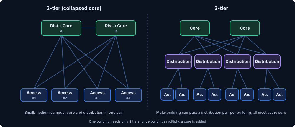
Why a separate core? The guide gives a telling number: connecting N distribution blocks directly takes N×(N−1)/2 links. With a core, each distribution needs two links, so N×2. For three buildings the difference is small; for ten it is large. The core keeps link count linear.
3. The 2-tier design: collapsed core
In a small campus a dedicated core switch is wasted money. The answer: put the distribution and core roles on the same pair of switches. This is the collapsed core. Access switches connect straight to that pair. One terminal acts as both district hub and city center.
When do you move to 3 tiers? The guide’s signals:
- When at least three distribution blocks connect together, a core becomes worth considering.
- When the distribution platform runs out of ports or bandwidth.
- When every service sits on one platform, the failure domain grows, and one bad change hits everyone.
- When access switches are spread across many buildings, fiber runs to a single center multiply.
A single building may need only access + distribution. A multi-building campus will most likely need all three.
4. Routed access: pushing Layer 3 to the access switch
In the classic design, Layer 2 runs between access and distribution and spanning tree blocks some links to prevent loops. With routed access, the Layer 3 boundary moves down to the access switch. The guide’s benefits:
- No STP loops or blocked links; both uplinks are active.
- Fewer protocols, simpler convergence.
The cost: the Layer 2 domain is limited to one wiring closet, access switches must route, and IP planning needs care. The guide also notes that many organizations need Layer 2 across closets. That is exactly where a fabric comes in.
5. Fabric: equal paths, rules in software
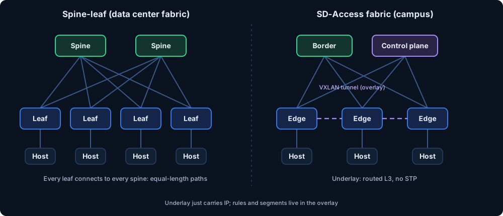
A fabric is the idea of “a simple IP network underneath, any Layer 2/3 service you want on top”. It has two faces.
5.1 Spine-leaf
The classic data center layout. Every leaf connects to every spine, and leaves do not connect to each other. Result: every leaf-to-leaf path is the same length (leaf → spine → leaf), and you add capacity by adding spines. Like a metro: the same number of transfers between any two stations.
5.2 SD-Access (the campus fabric)
Cisco SD-Access puts a fabric overlay on top of routed access and automates it with Catalyst Center (formerly DNA Center). The main parts, per the design guide:
| Part | Role |
|---|---|
| Underlay | Routed Layer 3 point-to-point links. No STP. LAN Automation builds it with IS-IS; OSPF/EIGRP can be set up manually. MTU 9100 is recommended to fit VXLAN overhead, 1550 minimum. |
| Overlay | Virtual networks (a VN is a VRF) and VXLAN-carried traffic. VXLAN adds at least 50 bytes. |
| Edge node | The access layer. Registers endpoints with the control plane, hosts the anycast gateway, does VXLAN encapsulation/decapsulation. |
| Control plane node | LISP map server/resolver. Answers “which edge (RLOC) is this endpoint (EID) behind?” Two active/active nodes are recommended. |
| Border node | Connects the fabric to the outside. The exit door. |
| Policy | SGT (16-bit group tag) for identity/group-based segmentation, integrated with TrustSec. |
The key idea is separating identity from location: the endpoint’s address (EID) is one thing, which edge it sits behind (RLOC) is another. Plug the device in somewhere else and its policy and address follow. The guide also mentions BGP EVPN VXLAN as an open-standards alternative: pick it for multi-vendor environments that don’t need full SD-Access automation.
One more term: a fabric site is a location with its own border, control plane and edge nodes.
6. Cloud design
The cloud doesn’t replace the layers, it rents out one side of them. From an enterprise network view, watch for:
- Virtual network: an isolated IP space and subnets allocated to you (like a VPC/VNet). Don’t overlap it with your own addressing plan.
- Connectivity: IPsec VPN, a private circuit, or SD-WAN between campus/branch and cloud. The cloud edge becomes part of your design.
- Shared responsibility: the provider runs the physical layer; you design routing, security and segmentation of your traffic.
- Many clouds and branches: instead of wiring each branch to the cloud one by one, use a central management/edge layer (such as SD-WAN, ENCOR 1.2) to keep the design simple.
For this item, remember that the cloud is designed as an extension of your network: identity, segmentation and addressing should stay consistent with the campus.
7. Which one, when?
| Situation | Design |
|---|---|
| One building, small/medium | 2-tier (collapsed core) |
| Many buildings, ≥3 distribution blocks, growth expected | 3-tier |
| L2 across closets + strong segmentation + automation | SD-Access fabric |
| Data center, heavy east-west traffic | Spine-leaf |
| Multi-vendor, want open standards | BGP EVPN VXLAN |
| Apps live in the cloud | Cloud connectivity + SD-WAN-aligned design |
8. Simulation: try it yourself
Three small experiments: how a core cuts the link count, who is hit when a switch fails, and what changes in SD-Access when a host moves.
9. Check yourself
- How many links to connect 6 distribution blocks directly, and via a core? (15 and 12)
- Which two roles merge in a collapsed core? (distribution + core)
- In SD-Access, who tracks which edge an endpoint is behind? (the control plane node, via LISP)
- Routed access’ gain over STP? (no blocked links, both uplinks active)
Sources
- Cisco Campus LAN and Wireless LAN Solution Design Guide
- Cisco Software-Defined Access Design Guide
- ENCOR 350-401 v1.2 blueprint (PDF)
The cloud section is general design knowledge, not a quote from Cisco guides. Next item: 1.1.b, high availability.